Zero-sequence voltage protection is a vital protection scheme in power systems specifically designed for ground faults, particularly single-phase-to-ground faults. It is widely employed in systems with an ungrounded neutral, a neutral grounded via an arc-suppression coil (Petersen coil), or a low-resistance grounded neutral. The following provides a detailed explanation from three aspects: principle, function, and setting calculation.
1. zero-sequence voltage protection Principle
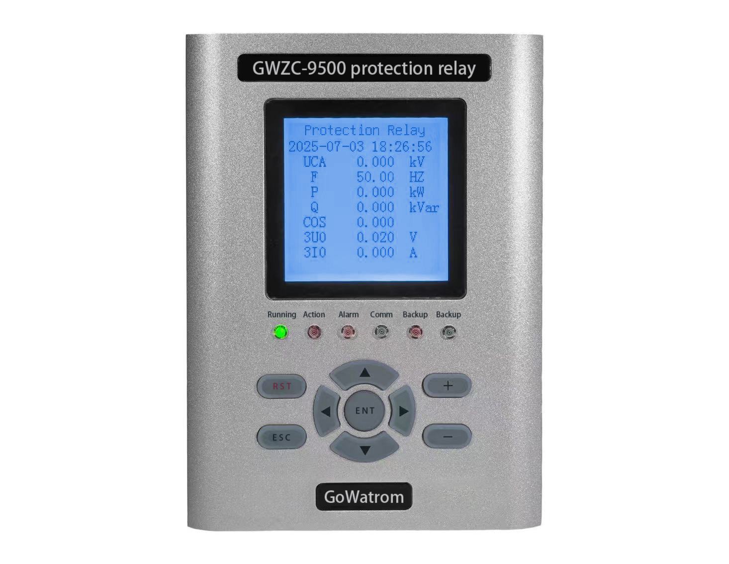
Zero-sequence voltage (3U₀) is derived from the phasor sum of three-phase voltages:3U₀ = U_A + U_B + U_C
Normally balanced system: Phasor sum ≈ 0 (3U₀ ≈ 0).
Ground fault: Voltage collapse in faulted phase generates substantial 3U₀ (3U₀ > 0).
Measurement methods:
Dedicated zero-sequence VT: Broken-delta connection of three-phase VTs directly outputs 3U₀.
Digital calculation: Protection relays compute 3U₀ via algorithms.
Physical significance:
3U₀ is a sensitive indicator of ground faults, especially in:
Ungrounded (IT) systems
Resonant-grounded (arc-suppression coil) systems
High-resistance grounded systems.
2. zero-sequence voltage protection Functions (IEEE C37.2 Device Function 59N)
1).Ground fault detection
High-sensitivity detection of single-line-to-ground (SLG) and double-line-to-ground (DLG) faults.
Critical for high-impedance ground faults (e.g., tree contact, cable degradation) where zero-sequence current (3I₀) protection may fail.
2).Backup protection
Provides backup tripping when 50N/51N (zero-sequence current) protection fails.
3).Insulation monitoring
Continuous 3U₀ supervision warns of insulation deterioration (e.g., VT failure, intermittent grounding).
4).Directional discrimination aid
Enables fault directionality (bus vs. line) with directional element 67N.
3.zero-sequence voltage protection Functions Setting Calculations (IEC 60255 Series)
Settings follow dependability, security, and selectivity principles:
(1) Pickup Setting (U₀>)
Base value: Normal system unbalance voltage (typically < 1–3% V_ph)
Formula:U₀> = K_rel × U_unb_max
K_rel: Reliability factor (1.5–2.5, covering transients/harmonics).
U_unb_max: Maximum measured unbalance voltage.
Typical ranges:
Effectively grounded systems: 5–10% V_ph
Non-effectively grounded systems: 10–30% V_ph
Example: 10kV ungrounded system (V_ph = 5.77 kV), U_unb_max = 0.5% V_ph = 29 V, K_rel=2.0 → U₀> = 58 V (≈1% V_ph).
(2) Time Delay (T)
Purpose: Immunity against transients (switching/lightning) and coordination.
Setting rules:
Selectivity: Time grading with downstream protection (Δt = 0.3–0.5 s).
Instantaneous element: Only used with secure VT failure blocking (t ≈ 0.1 s).
Non-effectively grounded systems:
Alarm stage: 0.5–1.0 s
Trip stage: 1.0–5.0 s
(3) Sensitivity Verification
Verify for minimum fault at protection boundary:
K_sen = U₀_min / U₀> ≥ 1.5
U₀_min: Minimum 3U₀ at relay location for metallic fault at remote end (calculated via system modeling).
Critical Application Notes
1).VT failure blocking (Device 60FL):
Mandatory to prevent maloperation (3U₀ may reach 33% V_ph during VT failure).
2).Harmonic immunity:
Use filters with >20 attenuation ratio for 3rd harmonics (e.g., transformer inrush).
3).Grounding system adaptation:
Ungrounded systems: Primary protection.
Effectively grounded systems: Supplemental to 50N/51N (high-impedance faults).
International Standards References:
IEC 60255-151: Measuring relays functional requirements
IEEE C37.95: Guide for protective relay applications to power transformers
IEEE Std C37.100.1: Standard for protective relay terminology
IEC 61869: Instrument transformer standards
Zero-sequence voltage protection (59N) provides critical ground fault detection security in non-effectively grounded systems and enhances high-resistance fault coverage in all networks when properly set per international standards.
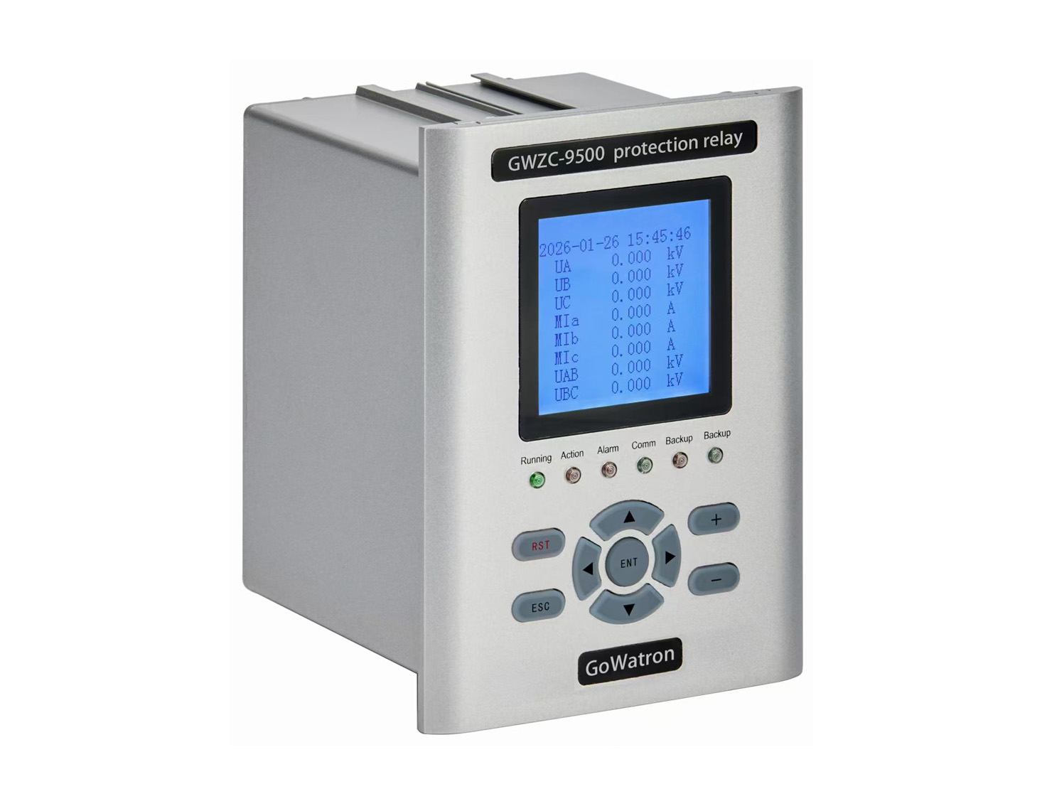
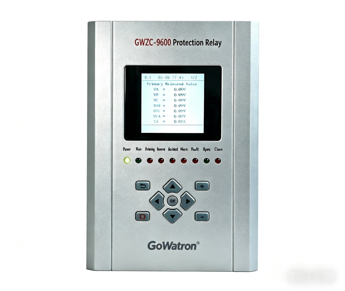
Both our line protection relays and transformer protection relays feature zero-sequence voltage protection. Feel free to inquire for procurement!