Back to smartelemfg Home
Contact us Merchants settle in
Back to smartelemfg Home
Home -Technical

Transformer Protection Configuration Principles

Source: Maxwell He 2025-08-11 16:35:30

Introduction​
       Transformer protection relay is critical for maintaining power system reliability. A well-designed ​transformer protection configuration​ must balance speed, selectivity, and sensitivity to prevent equipment damage and outages. ​Primary protection​ (e.g., differential and gas protection) acts instantly for internal faults, while ​backup protection​ (e.g., overcurrent, zero-sequence) provides redundancy for extended coverage. This guide covers key principles, settings, and coordination to optimize ​transformer protection​ schemes for different transformer types and voltage levels.

​1. Basic Configuration Principles​

  • Primary protection takes priority: Differential and gas relays must respond first to internal faults.
  • ​Backup protection ensures full coverage: Overcurrent and zero-sequence schemes protect adjacent equipment if primary protection fails.
  • ​Non-electrical protection is essential: Gas, pressure, and temperature relays complement electrical protections.

​2. Primary Protection Setup​

  • ​Differential protection: Mandatory for transformers ≥10MVA, with harmonic restraint to avoid inrush misoperation.
  • ​Gas protection (Buchholz relay)​: Triggers alarms (minor faults) or trips (severe faults) in oil-immersed transformers.

​3. Backup Protection Setup​

  • ​Overcurrent protection: Voltage-restrained or directional overcurrent for selective fault isolation.
  • ​Zero-sequence protection: Neutral grounding determines the scheme (direct = overcurrent; gap = overvoltage + overcurrent).

4. Special Transformer Protections​

  • ​Autotransformers: Require additional zero-sequence protection for common winding faults.
  • ​Dry-type transformers: Rely on differential protection and temperature monitoring.

​5. Coordination & Settings​

  • ​Differential settings: Minimum pickup = 0.2–0.5× rated current; restraint ratio = 0.3–0.6.
  • ​Time grading: Backup delays must exceed primary protection + breaker time (e.g., 0.3–0.5s margin).

​6. CT/PT Requirements​

  • Differential CTs: Identical ratios and dedicated cores to avoid imbalance.
  • ​Zero-sequence CTs: Polarized toward the transformer neutral.

​7. Example: 110kV Oil Transformer Protection​

  • Primary:Differential + Gas (Buchholz)+Instant trip
  • Backup HV:Directional Overcurrent+Delayed trip
  • Backup LV:Voltage-Restrained Overcurrent+Delayed trip
  • Neutral:Zero-Sequence (direct/gap)+Trip/alarm

​8. Key Considerations​

  • ​Inrush restraint: Prevent false trips during transformer energization.
  • ​CT saturation: Mitigate with high-impedance differential or digital relays.
  • ​Redundancy: EHV transformers (e.g., 500kV) need dual primary protections.

By following these ​transformer protection configuration​ principles, engineers can ensure fast fault clearance, minimize downtime, and enhance grid resilience.


Product recommendations More
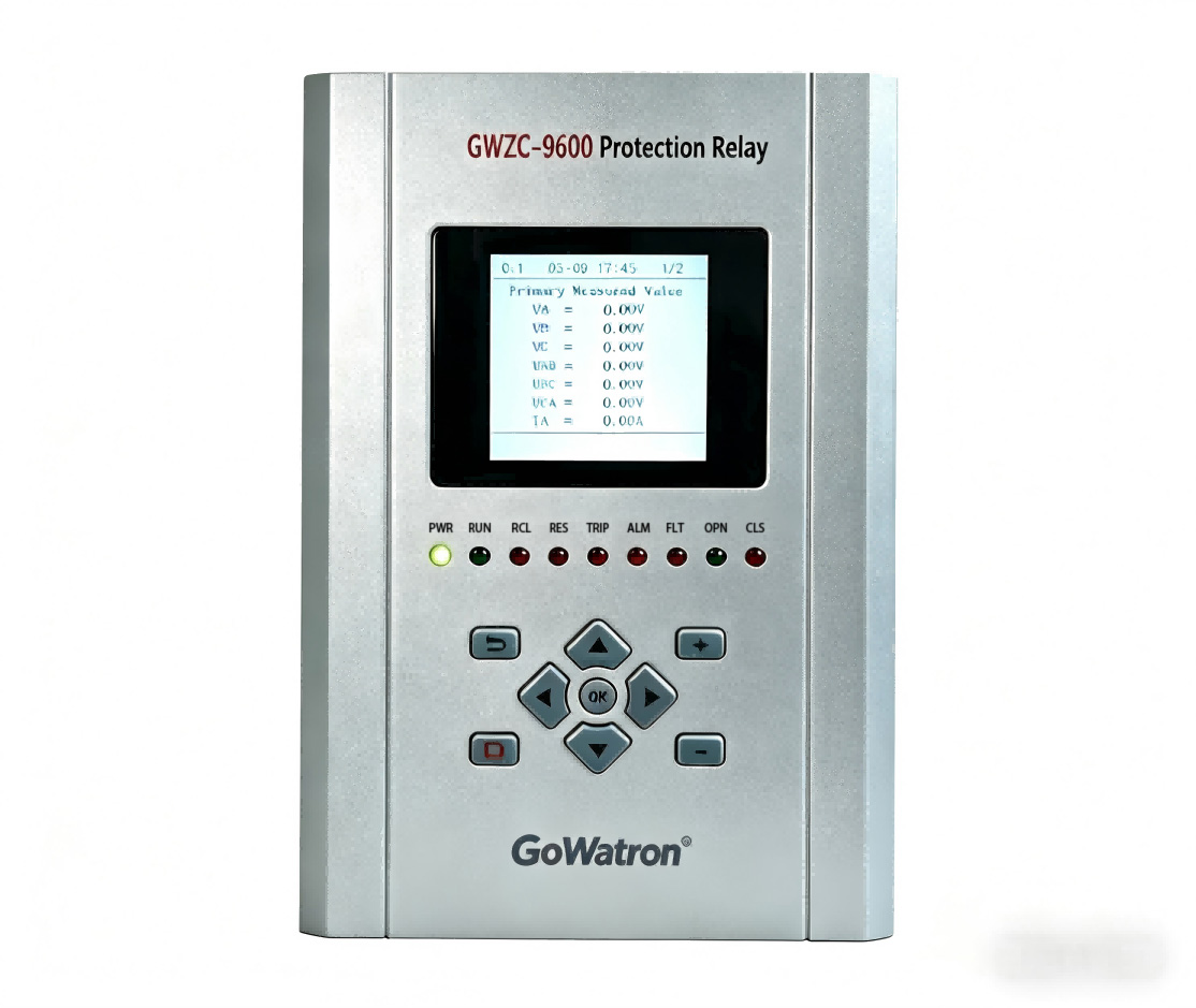
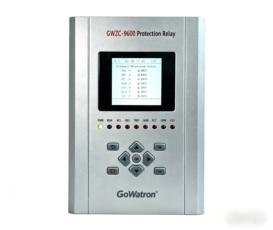
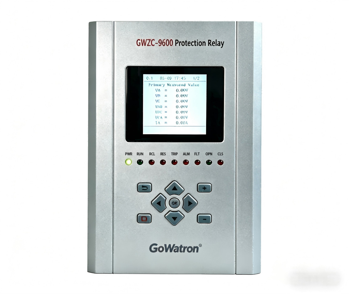
GWZC-9521 Distribution transformer protection relay
detail
GWZC-9621 Transformer protection relay
detail
GWZC-9621C Transformer Differential Protection Relay (87T)
detail
GWZC-9692 Transformer Backup Protection Relay
detail
GWZC-9693 Transformer Non-Electrical Protection Relay
detail
Technical More
GWZC-9694 Main Transformer On-load Tap Changer Control Relay
Transformer Magnetizing Inrush Current: Causes, Effects & Prevention
Inrush current occurs when transformers are energized, reaching 68× rated current due to magnetic core saturation and residual flux. Characterized by high harmonics, asymmetry, and decay, it risks mechanical stress and protection misoperation. Prevention includes harmonicbased restraint algorithms, controlled switching, and waveform analysis to ensure system reliability.
2025/07/22
Transformer Non-Electrical Protection
Transformer Differential Protection vs. Line Differential Protection: Key Differences
Transformer differential protection safeguards transformers by addressing inrush currents and phase shifts, while line differential protection focuses on transmission lines, compensating for capacitive currents and ensuring data synchronization. Both compare current differentials but differ in implementation due to distinct equipment characteristics—transformers (electromagnetic coupling) versus lines (distributed parameters and communication delays).
2025/07/18
Transformer Non-Electrical Protection
Transformer Non-Electrical Protection: Types, Functions & Working Principles​
​Transformer Non-Electrical Protection​ refers to protective measures based on monitoring non-electrical parameters, addressing faults that electrical relays cannot directly detect. These safeguards are critical for preventing insulation failure, internal faults, and catastrophic damage in power transformers.
2025/07/15
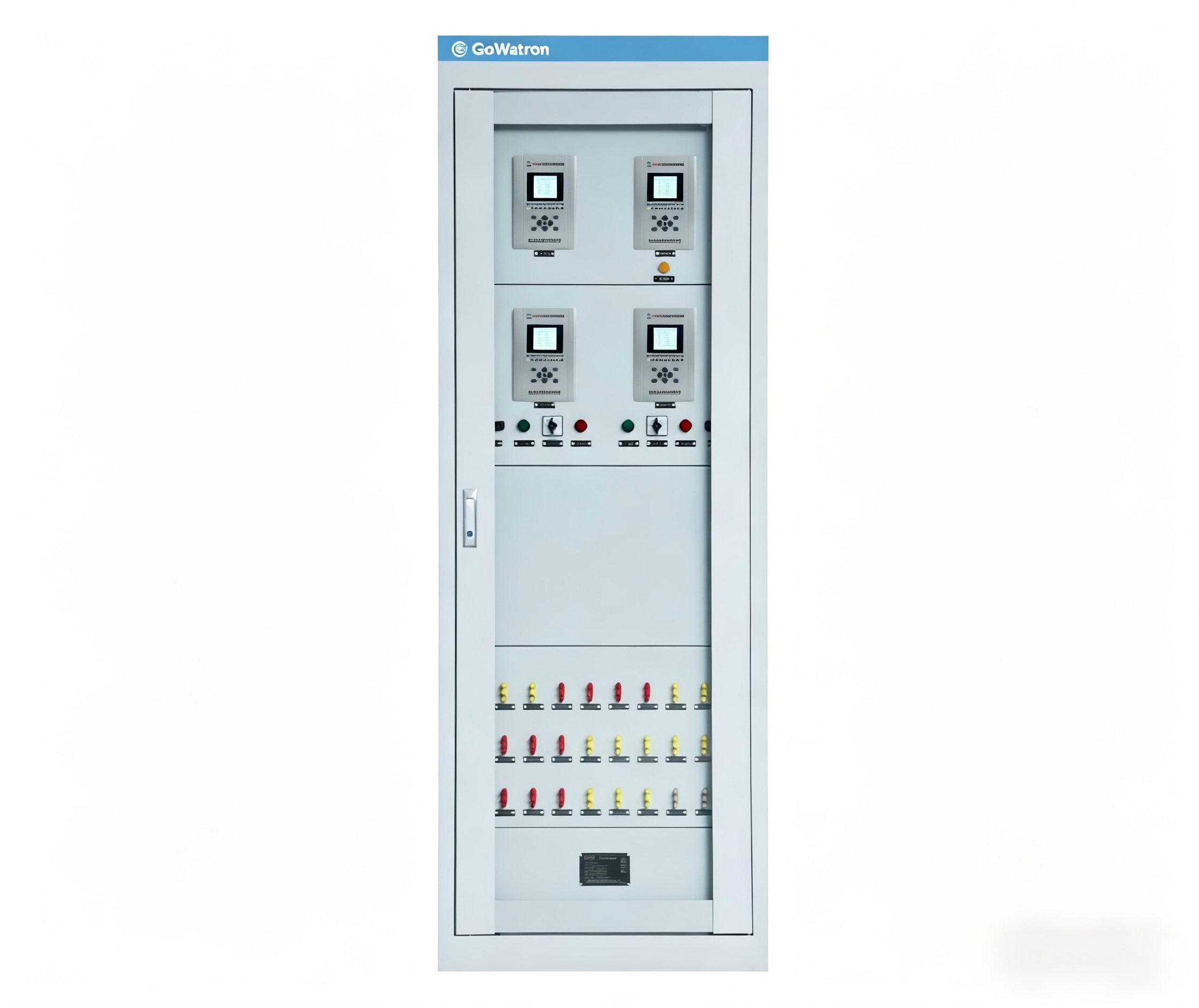
Transformer Protection Relay Panel
Renovation Scheme for Unattended Automatic System of Hydropower Station
The core of the transformation of the unattended automation system for hydropower stations is to upgrade the traditional manually attended power station into a modern intelligent power station with "unattended operation and minimal personnel on duty" through computerized monitoring, intelligent sensing, reliable communication and remote centralized control. It realizes remote monitoring, automatic control, fault self-diagnosis and safety early warning, greatly reducing labor costs and improving operational efficiency and safety. Among them, the secondary electrical system, as the "nervous system, brain and safety line of defense" of the power station, is the core support for the unattended transformation. Without a reliable secondary system, true unattended operation cannot be achieved. Therefore, this integration will focus on improving the detailed content of secondary electrical equipment while retaining the full process details of the transformation.
2026/04/21
Inquiry Consultation
+86-17621210051
+86-17621210051
+86-17621210051
+86-17621210051
home product email
live chat
my