Back to smartelemfg Home
Contact us Merchants settle in
Back to smartelemfg Home
Home -Technical

Motor Magnetic Balance Differential Protection Relay: Principles, Applications

Source: 2025-07-10 17:46:05

Introduction to Magnetic Balance Differential Protection Relay​

          The motor magnetic balance differential protection relay is an internal fault protection device used for medium- and high-voltage motors, detecting winding faults by comparing the current difference between the motor’s input and neutral terminals.

​Working Principle of Magnetic Balance Differential Protection​

Basic Principle: Uses CTs (current transformers) installed at both ends of the motor to measure current and compare vector sums.
                  Normal operation: I 1 +I 2 ≈0 (magnetic flux balance)
                  Internal fault: I 1 +I 2 =I d (differential current)

Protection Algorithm:
          Differential current: I d =I 1 +I 2
          Restraint current: I r =(∣I 1 ∣+∣I 2 ∣)/2
          Operation criterion: I d >I set and I d >k×I r (where k is the restraint coefficient, typically 0.3–0.5)

Application Scope of Magnetic Balance Differential Protection​

          ​Voltage level: 3 kV and above (medium/high-voltage motors)
          ​Power range: Typically motors above 200 kW
​         Applications: Critical process motors in petrochemical, metallurgical, and power industries

​Key Functions of Magnetic Balance Differential Protection Relay​

          ​High Sensitivity: Detects 5–10% inter-turn short circuits
          ​Fast Operation: Typical response time of 20–50 ms
          ​CT Saturation Resistance: Uses ratio restraint characteristics to prevent false trips
          ​Optional Features:
                Second harmonic restraint (prevents inrush current misoperation)
                CT open-circuit detection
                 Differential current alarm

​Practical Recommendations for Magnetic Balance Differential Protection​

​Relay Selection:

          Choose dedicated motor differential protection relays (e.g., SEL-710, 7UT612)
          CT matching: Use identical ratios with ≤5% error

​Setting Calculation:

          Starting current: I set =(0.2–0.5)I n (rated current)

          Restraint coefficient: k=0.3–0.5

          Sensitivity check: K sen ≥2

​Field Testing:

          Perform six-vector diagram tests to verify CT polarity
          Load testing to ensure differential current <5% of rated value
          Simulate internal/external faults to verify operation logic
Product recommendations More
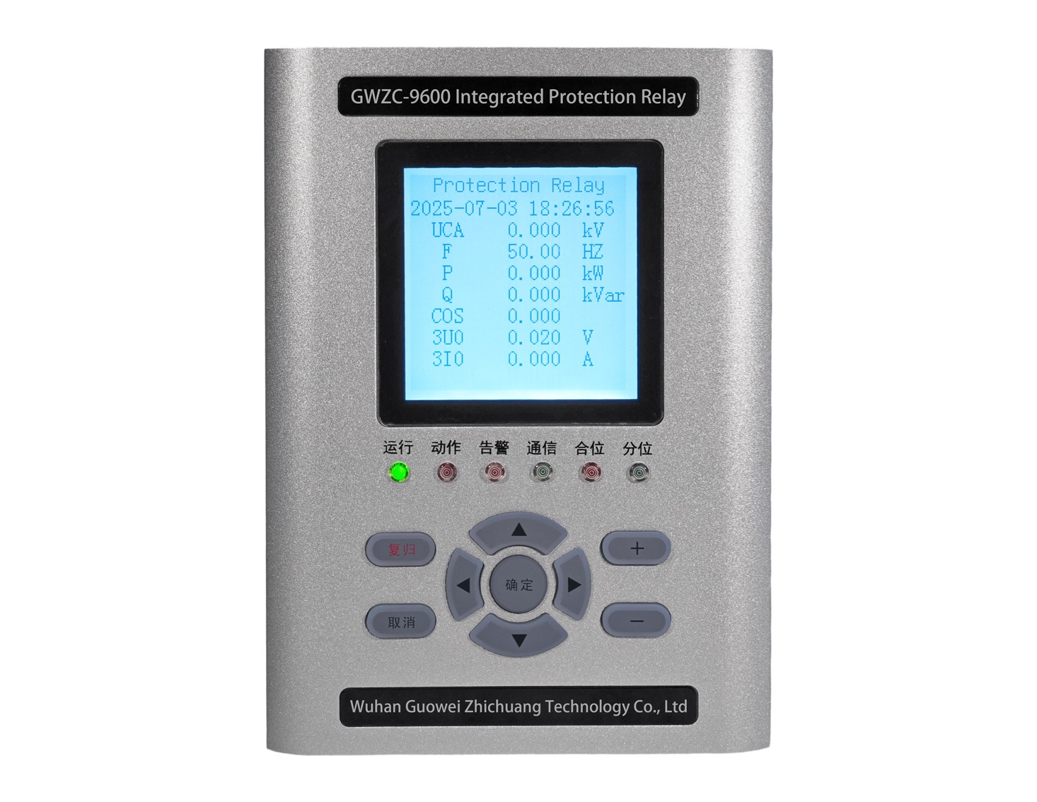
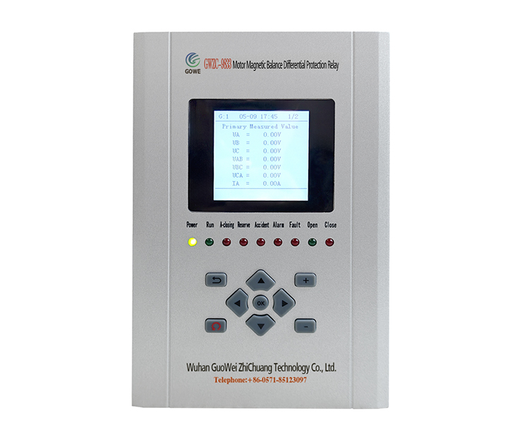
GWZC-9833 Motor Magnetic Balance Differential Protection Relay (87M)
detail
GWZC-9586 Low-voltage generator protection relay
detail
GWZC-9605 Cable insulation monitoring device (IMD)​​(ANSI 64)
detail
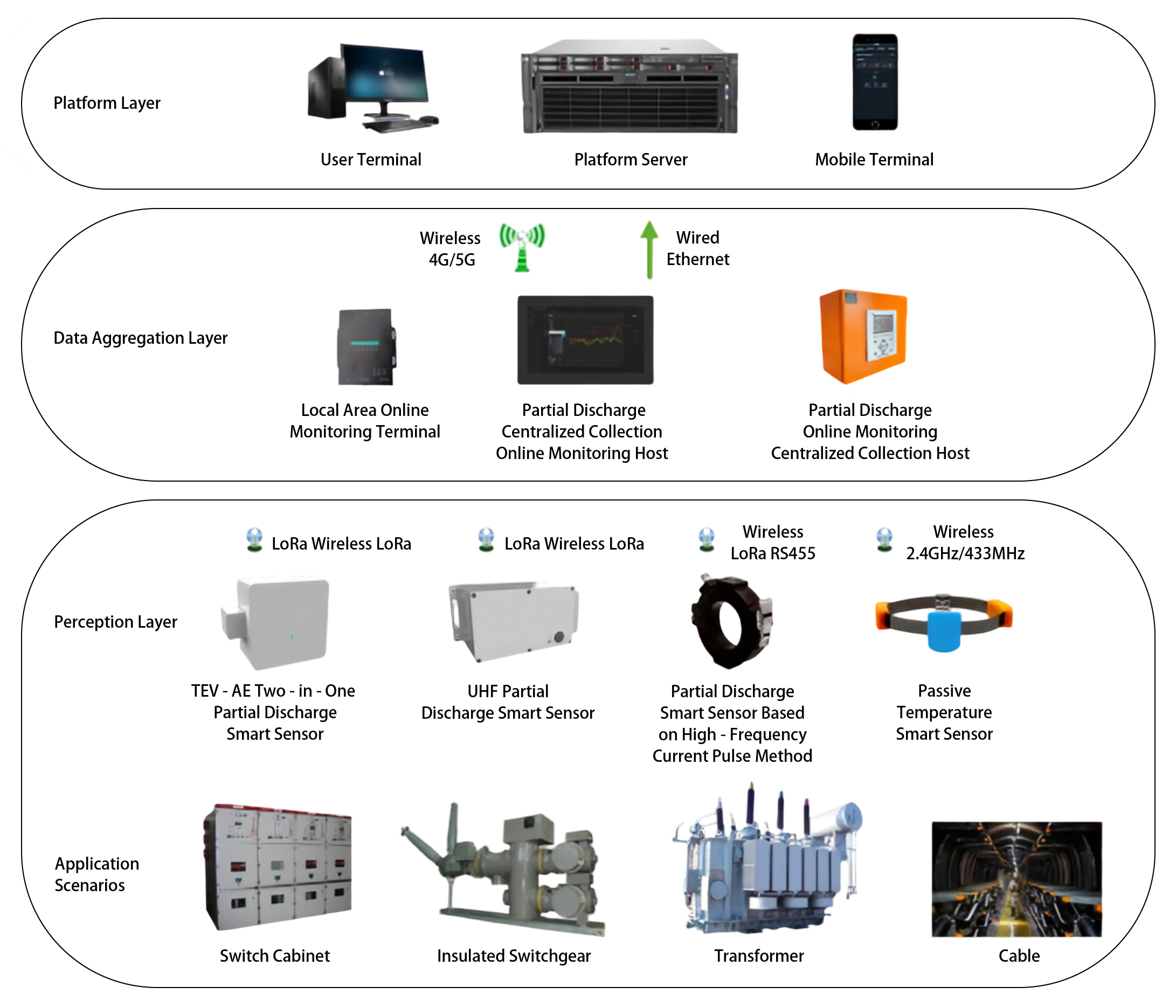
GOWE-9000 Partial discharge online monitoring system
detail
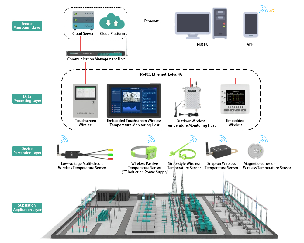
GOWE-9000 Wireless Temperature Monitoring System for Substations
detail
Technical More
Generator Protection Panel
Generator Protection Relay Panel : Composition and Function
Integrating protection, measurement, and communication, the Generator Protection Relay Panel can realize the protection and control of various units, enabling unattended or minimally attended operation. It can achieve generator differential protection, rotor earth fault protection, stator earth fault protection, excitation protection, overcurrent protection, overvoltage protection, overload protection, backup protection, etc.
2025/11/25
Main Transformer-Protection Panel
Transformer Protection Relay Panel:Composition and Function
Transformer Protection Relay Panel is primarily used in automation systems for substations and distribution stations in power systems of 11kV, 33kV, 132kV and above. Its main function is to ensure that the transformer can promptly trip the faulty circuit in case of overload, short circuit, gas relay activation, and other abnormal operating conditions, thereby protecting the main transformer from damage and preventing the expansion of faults.
2025/11/24
Feeder Protection Relay
Common Protection Functions for Feeder Protection Relays?
Feeder protection relays are a type of line protection relay and serve as critical devices in distribution systems for protecting power cables (feeders). They integrate multiple protection functions to achieve comprehensive, reliable, and selective protection. Below are the commonly used protection functions of feeder protection relays, along with their corresponding ANSI codes.
2025/11/14
Transformer protection relay
Transformer Differential Protection(ANSI 87T): Working Principle, Function, and Setting Calculation
The working principle of the Transformer Differential Protection Relay is based on Kirchhoff's Current Law. This law states that the sum of currents entering a node is zero. Ideally, for a healthy (non-faulted) transformer, the current entering the primary winding should equal the current leaving the secondary winding (after accounting for the transformer's turns ratio and phase shift).
2025/11/12
Inquiry Consultation
+86-17621210051
+86-17621210051
+86-17621210051
+86-17621210051
home product email
live chat
my