Back to smartelemfg Home
Contact us Merchants settle in
Back to smartelemfg Home
Home -Technical

Distance Protection in Transmission Lines: Principles and Practical Considerations​

Source: Smartelecmfg 2025-07-10 17:18:51

Introduction to Distance Protection​

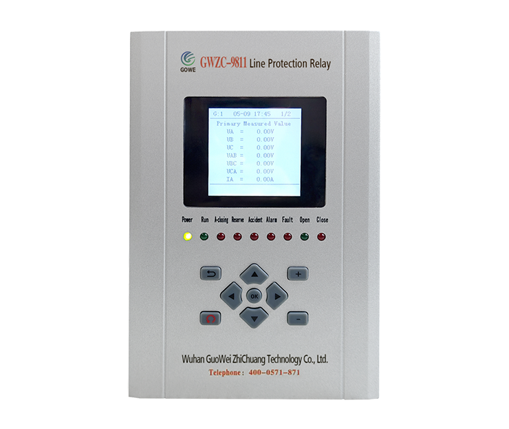
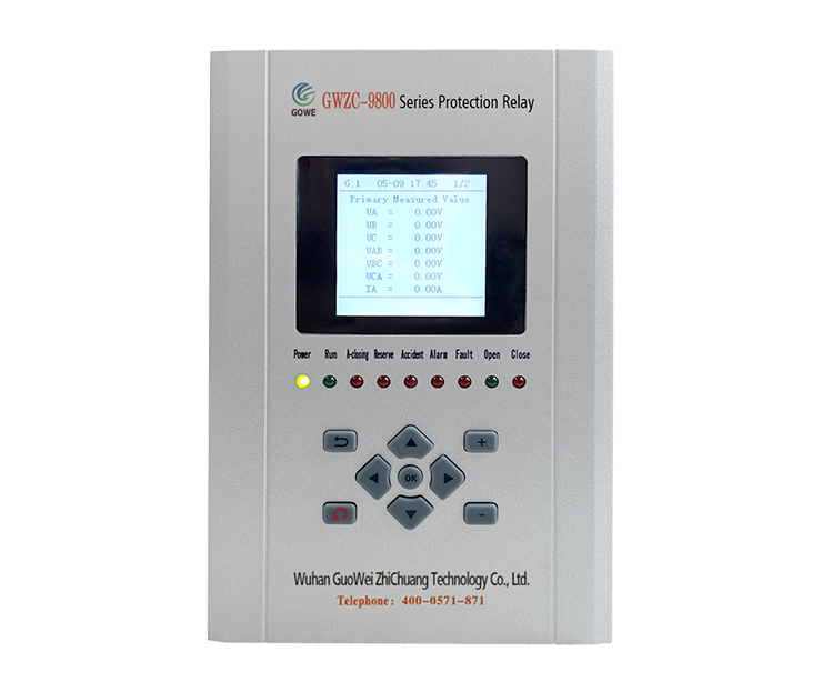
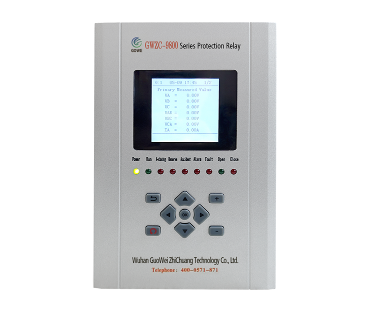
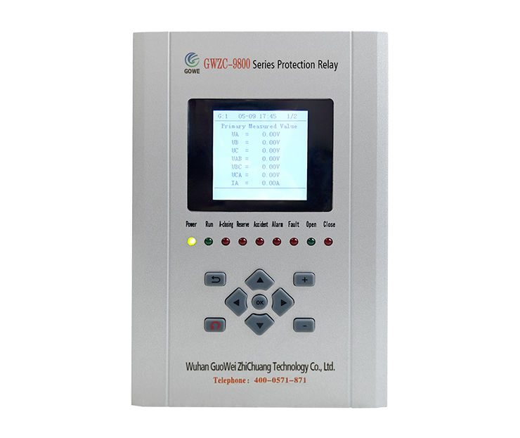
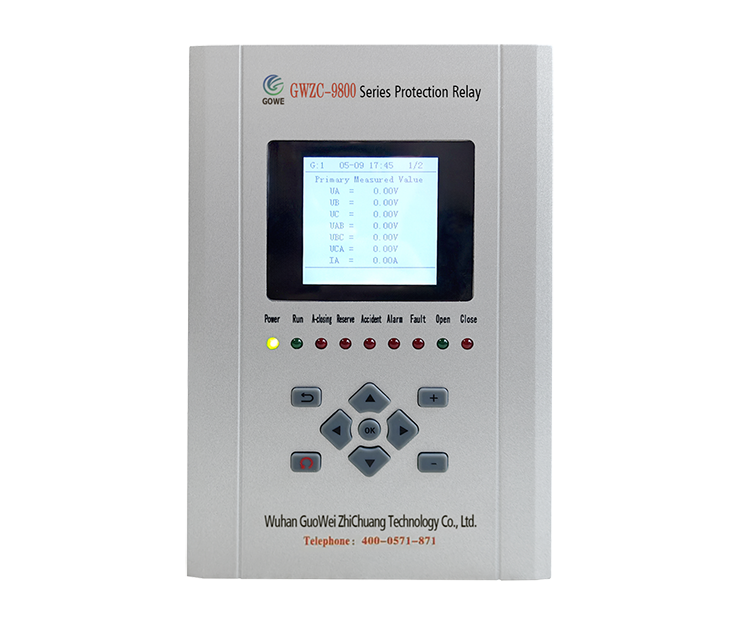
          Distance protection is a core protection method for high-voltage transmission lines, implemented using ​distance protection relays​ that determine fault location by measuring the impedance between the fault point and the protection installation point and executing tripping accordingly.

​Working Principle of Distance Protection​

​Impedance Measurement Principle in Distance Protection:

          Basic formula: Z= V /I(measured impedance)
          Uses hexagonal characteristic impedance relays (R-X plane)
          Typical protection zone settings:
                  Zone Ⅰ: 80-85% of line length (instantaneous operation)
                  Zone Ⅱ: 100% of own line + 50% of adjacent line (0.3-0.5s delay)
                  Zone Ⅲ: Backup protection (1-3s delay)

​Key Technologies in Distance Protection:
          Directional discrimination (prevents maloperation for reverse faults)
          Power swing blocking (prevents tripping during system oscillations)
          PT/CT failure detection

​Application Scope of Distance Protection​

          Voltage levels: 110kV and above transmission lines
          Line length: Overhead lines >10km
          Particularly suitable for:
                  Multi-terminal power supply systems
                   Ring network configurations
                   Long-distance heavily loaded lines

​Key Functions of Distance Protection​

          ​Fault Location in Distance Protection: Accurately determines whether a fault is within the protection zone
          ​Fast Isolation in Distance Protection: Zone Ⅰ operates in typically <30ms
          ​Backup Protection in Distance Protection: Provides a complete graded protection scheme

​Practical Considerations for Distance Protection​

​Setting Calculation in Distance Protection:

          Must consider: Line parameters, system impedance, coordination with adjacent line protection
          Typical settings (example for 220kV line):
                  Z =0.85×Z line
            Z =1.2×(Z line​ +0.5×Z next )
            Z =1.2×(Z line +Z next +Z transformer)

​Troubleshooting Common Issues in Distance Protection:

​False Tripping in Distance Protection:
          Check CT/PT polarity
          Verify secondary circuit wiring
          Test relay characteristic curve

​Failure to Trip in Distance Protection:
          Measure secondary voltage/current
          Check relay power supply
          Test trip circuit

​New Technology Applications in Distance Protection:

          Digital protection (sampling rate ≥16 samples/cycle)
          Pilot-aided distance protection (communication-assisted)
          Adaptive distance protection (dynamic adjustment of characteristics)
Product recommendations More
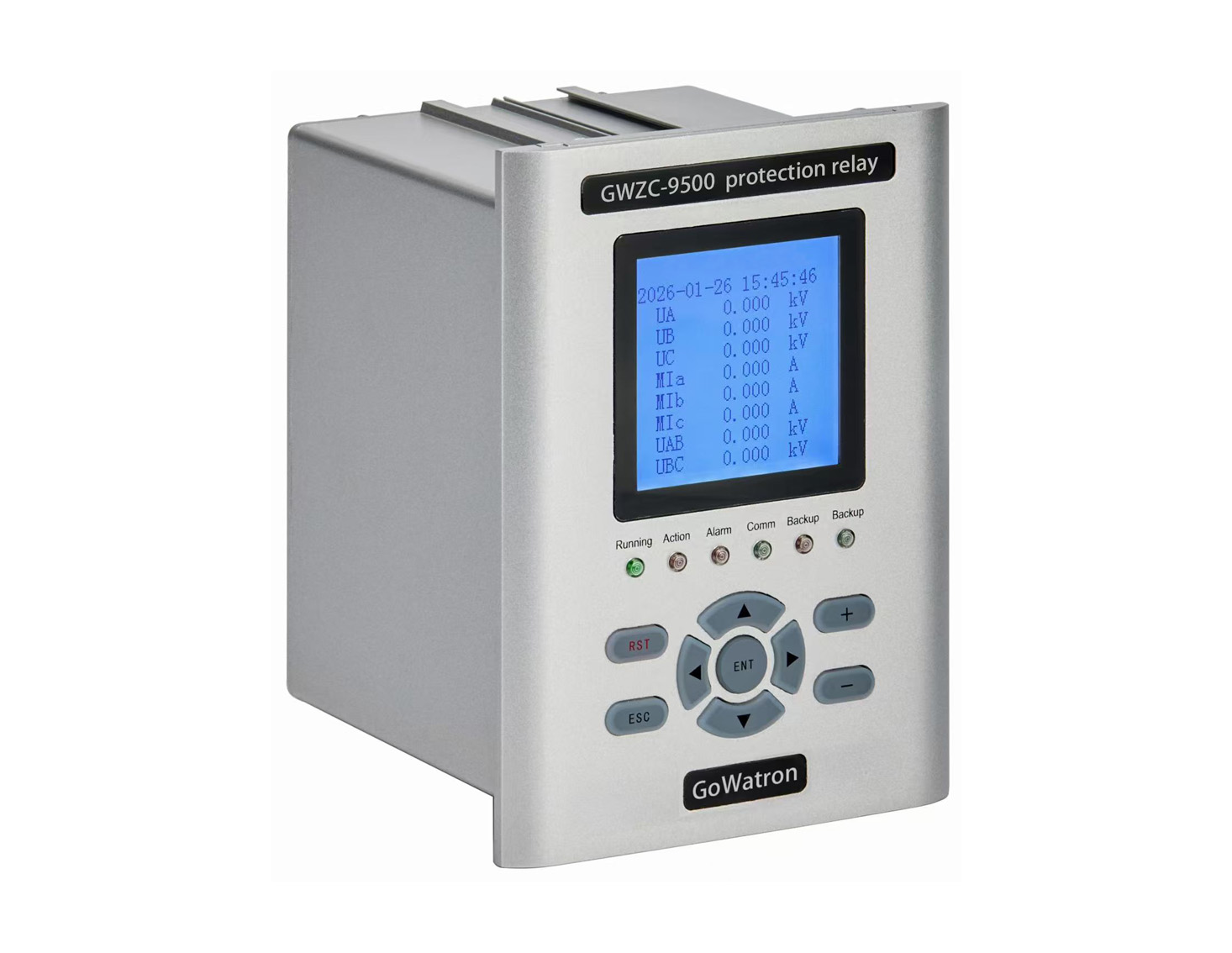
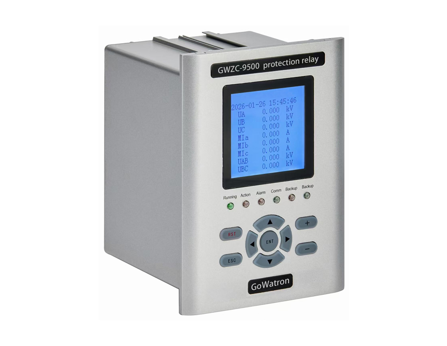
GWZC-9612 Distance protection relay(21 | 21G | 21FL)
detail
GWZC-9581 Low-voltage generator protection relay
detail
GWZC-9506 Cable insulation monitoring device (IMD)​​(ANSI 64)
detail
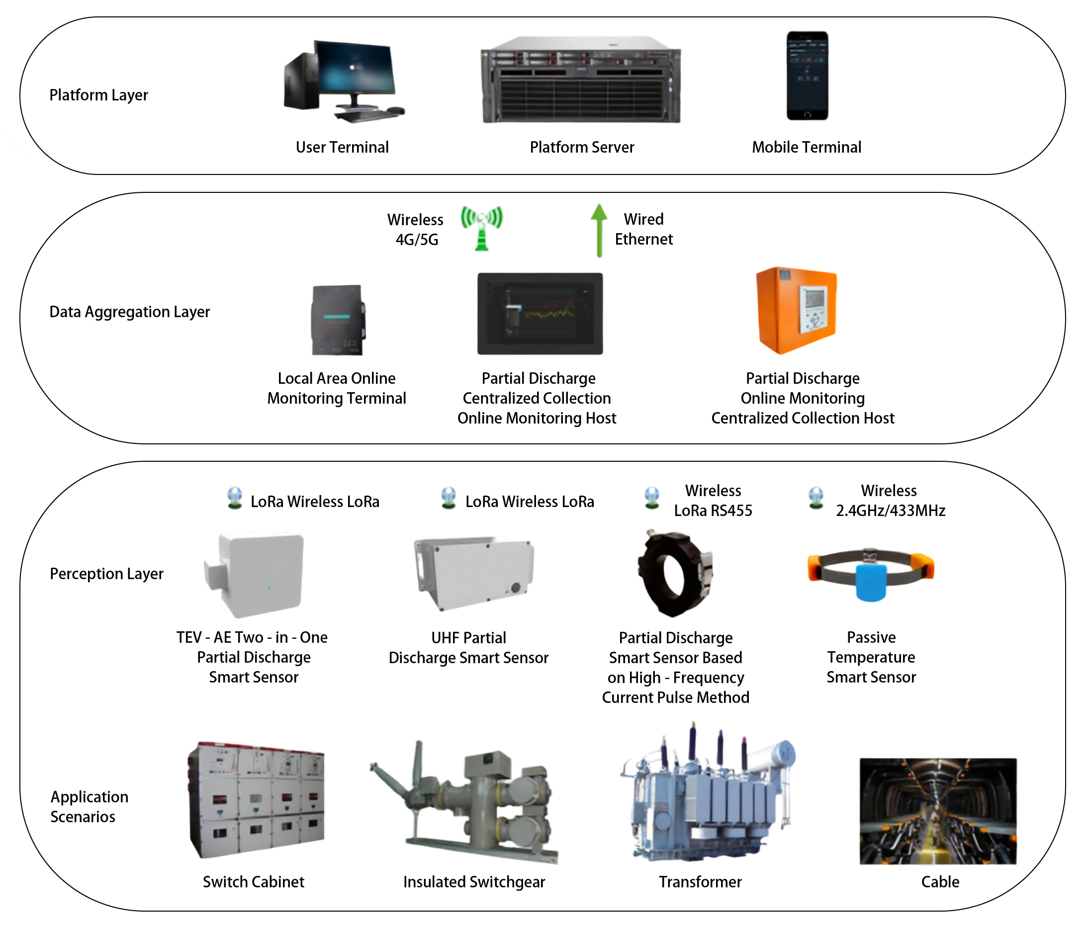
GOWE-9000 Partial discharge online monitoring system
detail
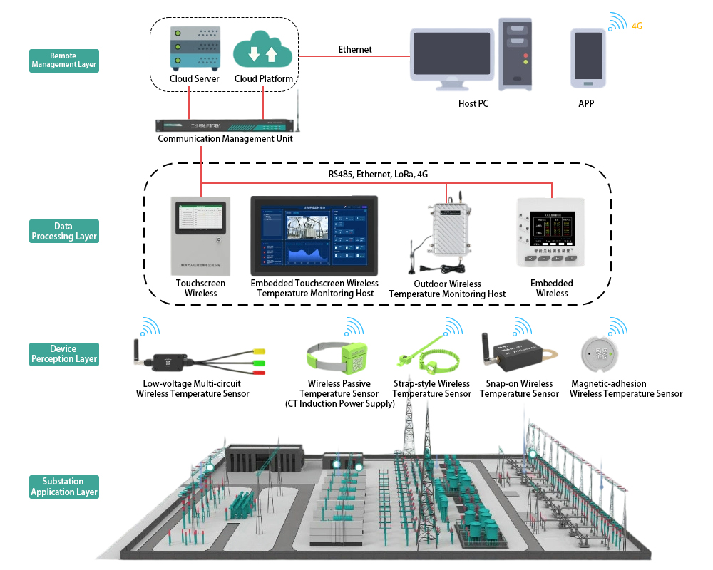
GOWE-9000 Wireless Temperature Monitoring System for Substations
detail
Technical More
Ground Distance Protection (21G)
Differences Between Phase-to-Phase Distance Protection (21P) and Ground Distance Protection (21G)
The core difference between phase-to-phase distance protection and ground distance protection lies in the selection of measured quantities, fault response range, and connection methods. They complement each other to form a complete distance protection system for high-voltage transmission lines, both following the basic principle: operation if the measured impedance is less than the setting impedance.
2026/03/04
Distance Protection
Distance Protection in Transmission Lines: Principles and Practical Considerations​
Distance protection is a core protection method for high-voltage transmission lines, implemented using ​distance protection relays​ that determine fault location by measuring the impedance between the fault point and the protection installation point and executing tripping accordingly
2025/07/10
Transformer Protection Relay Panel
Renovation Scheme for Unattended Automatic System of Hydropower Station
The core of the transformation of the unattended automation system for hydropower stations is to upgrade the traditional manually attended power station into a modern intelligent power station with "unattended operation and minimal personnel on duty" through computerized monitoring, intelligent sensing, reliable communication and remote centralized control. It realizes remote monitoring, automatic control, fault self-diagnosis and safety early warning, greatly reducing labor costs and improving operational efficiency and safety. Among them, the secondary electrical system, as the "nervous system, brain and safety line of defense" of the power station, is the core support for the unattended transformation. Without a reliable secondary system, true unattended operation cannot be achieved. Therefore, this integration will focus on improving the detailed content of secondary electrical equipment while retaining the full process details of the transformation.
2026/04/21
Generator Protection Panel
Generator Protection Relay Panel : Composition and Function
Integrating protection, measurement, and communication, the Generator Protection Relay Panel can realize the protection and control of various units, enabling unattended or minimally attended operation. It can achieve generator differential protection, rotor earth fault protection, stator earth fault protection, excitation protection, overcurrent protection, overvoltage protection, overload protection, backup protection, etc.
2025/11/25
Inquiry Consultation
+86-17621210051
+86-17621210051
+86-17621210051
+86-17621210051
home product email
live chat
my