The core of the transformation of the unattended automation system for hydropower stations is to upgrade the traditional manually attended power station into a modern intelligent power station with “unattended operation and minimal personnel on duty” through computerized monitoring, intelligent sensing, reliable communication and remote centralized control. It realizes remote monitoring, automatic control, fault self-diagnosis and safety early warning, greatly reducing labor costs and improving operational efficiency and safety. Among them, the secondary electrical system, as the “nervous system, brain and safety line of defense” of the power station, is the core support for the unattended transformation. Without a reliable secondary system, true unattended operation cannot be achieved. Therefore, this integration will focus on improving the detailed content of secondary electrical equipment while retaining the full process details of the transformation.
I. Core Objectives of the Transformation
– Operation Mode: Cancel 24-hour on-site duty, realize unattended normal operation, and conduct regular on-site inspection and maintenance.
– Function Implementation: Full coverage of four remote functions (telemetry, remote signaling, remote control, remote regulation), and full automation and intelligence of secondary electrical equipment.
– Safety Guarantee: Automatic equipment fault alarm, protection action and emergency shutdown, reliable data storage, and in-place anti-misoperation locking of secondary circuits.
– Benefit Improvement: Reduce personnel and increase efficiency, optimize dispatching, extend equipment service life, reduce unplanned outages, and realize seamless linkage between the secondary system, primary equipment and remote centralized control.
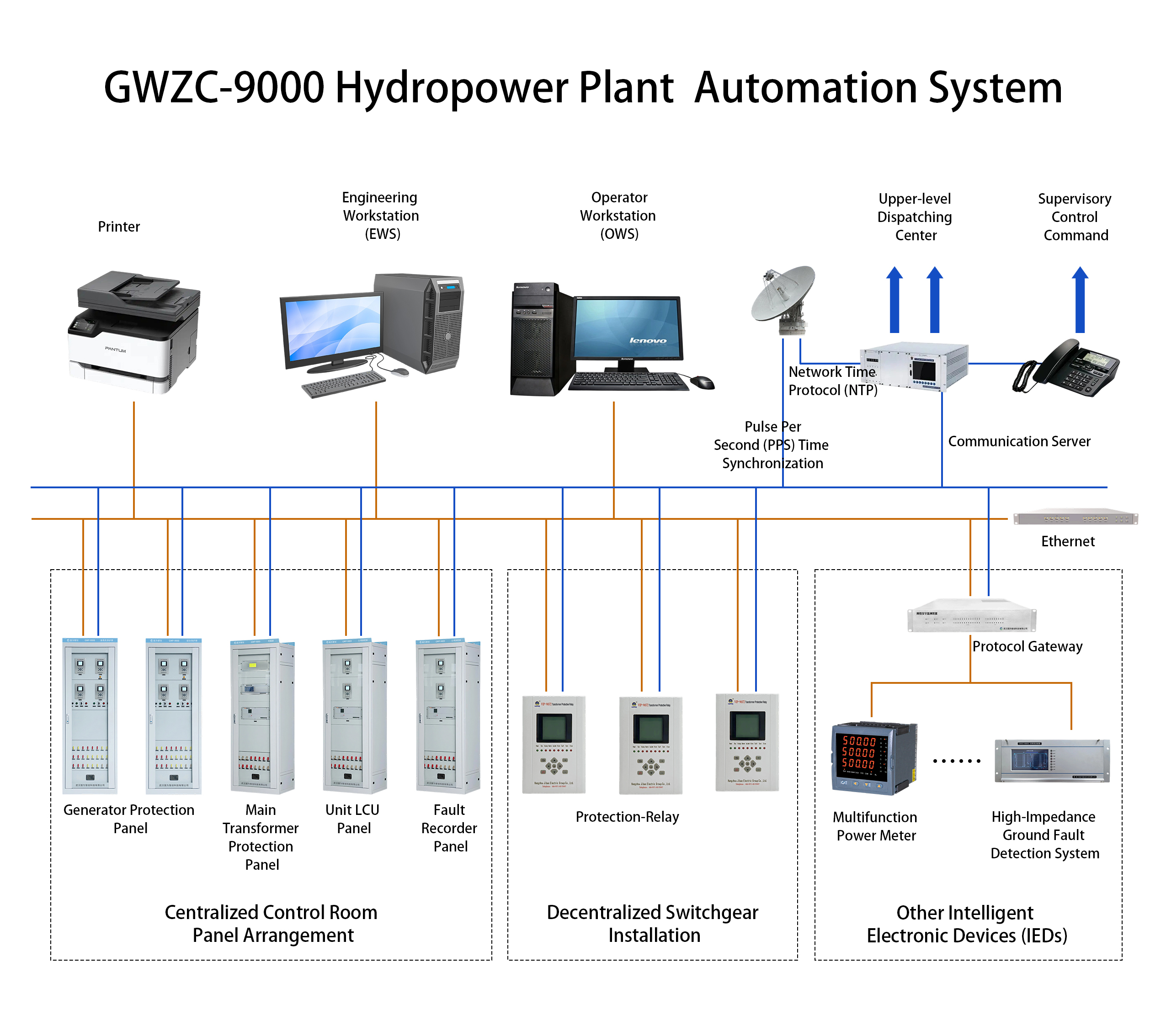
II. Overall System Architecture (Three Layers)
1. Process Layer (Equipment Layer)
– Intelligent Sensing: Water level gauge, pressure/flow transmitter, temperature/vibration/swing sensor, current/voltage transformer (CT/PT, core acquisition components of the secondary system).
– Actuators: Digital governor, microprocessor-based excitation regulator, intelligent valve/sluice controller, automatic pneumatic/hydraulic circuit.
– Basic Equipment: Unit automation components, local protection circuits, smart electricity meters, circuit breakers, isolating switches, etc. (providing control and protection objects for secondary equipment).
2. Local Control Layer (LCU Layer)
– Local Control Unit (LCU): Configured by object (unit LCU, common LCU, switchyard LCU, sluice LCU), it is the core equipment of the secondary electrical bay layer.
– Typical Configuration: PLC main controller (redundancy optional), digital input/output module, analog acquisition module, local touch screen/operation panel, local/remote changeover switch.
– Core Functions: Data acquisition (including various secondary electrical signals), logic control, local/remote switching, independent protection, fault recording, and seamless connection with governor, excitation and protection devices.
– Redundant Configuration: Redundancy of key PLCs, power supplies and communication ports to ensure local autonomous safety when communication is interrupted and guarantee the normal operation of secondary circuits.
– Related Content of Secondary Circuits: Unit temperature inspection (thrust bearing, guide bearing, stator winding, etc.), unit vibration/swing acquisition, unit overspeed/emergency shutdown linkage logic, mechanical brake automatic control, auxiliary system linkage, as well as control and interlocking circuits of circuit breakers and isolating switches.
3. Station Control/Remote Centralized Control Layer
– Main Control System: Operator workstations (2 units with redundancy), engineer workstation, history/communication server, network core switch, GPS/Beidou clock synchronization device, printer, which are the core components of the secondary electrical station control layer.
– Remote Centralized Control Center: Multi-station unified monitoring large screen, cloud platform, mobile APP (mobile phone/tablet monitoring and operation), realizing remote monitoring and operation of secondary equipment and alarm reception.
– Software Functions: Panoramic screen (including electrical primary/secondary system simulation diagram), trend curve, alarm pop-up window, operation record, automatic report generation, event recall, SOE (Sequence of Events) record, supporting fault waveform retrieval of secondary equipment.
III. Main Transformation Content and Subsystems
1. Computerized Monitoring System (Core)
– Upgrade and Transformation: Replace the old system with a hierarchical distributed full computerized monitoring system to realize communication linkage with all secondary electrical equipment.
– Key Functions:
– Unit one-key sequential control for start-up, shutdown, automatic grid connection and automatic load regulation (linking with secondary synchronization device, governor and excitation system).
– Full automatic operation and fault linkage switching of auxiliary (oil/gas/water) systems (realized through LCU secondary circuits).
– Intelligent monitoring and automatic power switching of station service power and DC system (core power supply of the secondary system).
– Hierarchical fault alarm (acoustic-optical + SMS/APP push), covering all abnormal signals of secondary equipment.
2. Hydrological and Hydraulic Structure Monitoring System
– Water Level Monitoring: Redundant configuration of upstream/tailwater levels with high-precision acquisition, data access to the monitoring system, and linkage with sluice secondary control circuits.
– Hydrological Measurement and Reporting: Automatic collection of rainfall, flow and reservoir water level, flood forecast calculation, providing data support for secondary system dispatching decisions.
– Sluice Control: Remote control, automatic interlocking and anti-misoperation of inlet valves/quick gates/spillway gates, whose control circuits are incorporated into the LCU secondary system.
– Hydraulic Structure Safety: On-line monitoring of dam seepage pressure, displacement and cracks (optional), monitoring signals access to the secondary monitoring system, and abnormal triggering of alarms.
3. Unit and Electrical Automation (Focus on Improving Secondary Electrical Part)
(1) Unit Body
– Governor: Full digital, remotely adjustable, fast response and high precision. Its secondary control part (digital electrical governor controller, frequency measurement, opening control circuit) is incorporated into the local LCU, supporting automatic start-up, shutdown, grid connection and load regulation, and linking with the emergency shutdown solenoid valve control circuit.
– Excitation: Microprocessor-based excitation with automatic voltage regulation, constant power factor and remote setting. Its secondary system (dual-channel redundant microprocessor-based excitation regulator, excitation power cabinet, de-excitation cabinet, overvoltage protection, rotor current/voltage acquisition circuit) communicates with the monitoring system to realize full automatic operation, fault self-protection and remote adjustability.
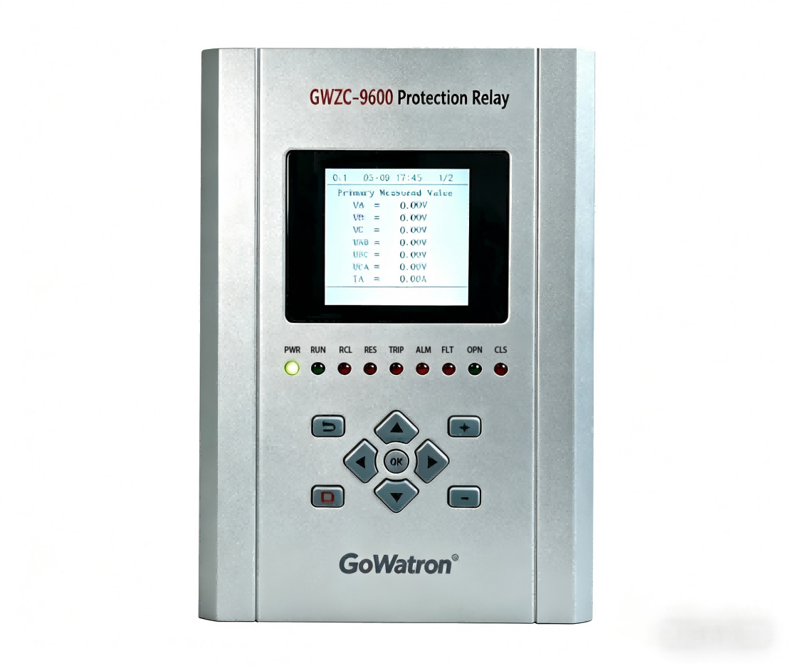
– Protection: Protection relay (overcurrent, overvoltage, overspeed, bearing temperature, excessive vibration, etc.), fault self-tripping and signal remote transmission, which is the core protection equipment of the secondary electrical system. For specific configuration, see the detailed description below.
(2) Secondary Electrical System (Detailed Introduction)
The secondary electrical system is the core of the unattended transformation, responsible for the monitoring, control, protection and communication of primary equipment. It is generally divided into the station control layer, bay layer and process layer. The specific equipment, functions and transformation requirements are as follows:
① Secondary Equipment and Functions of the Station Control Layer
– Main Equipment: Operator workstations (2 units with redundancy), engineer workstation, data server/history server, printer, GPS/Beidou clock synchronization system, core switch, firewall, vertical encryption device.
– Clock Synchronization System: Master clock + extended clock, providing unified time synchronization for protection, measurement and control, LCU and background, ensuring accurate timing of SOE (Sequence of Events) in case of faults and providing a reliable basis for accident analysis.
– Secondary Security Equipment (Mandatory Requirement): Firewall, vertical encryption authentication device, one-way physical isolation device, security audit and authority management, complying with the safety protection regulations of power monitoring systems, preventing network attacks and protecting the data security of the secondary system.
– Remote Control and Dispatching Communication System:
– Equipment: Remote Terminal Unit (RTU/remote communication unit), data network access equipment (SDH/optical modem/4G gateway), dispatching data network switch, vertical encryption authentication device (required for power security zone Ⅰ/Ⅱ).
– Functions: Upload four remote data to the local dispatching/county dispatching/centralized control center, support protocols such as IEC60870-5-104, 101, CDT and Modbus TCP, receive load plans and voltage regulation instructions issued remotely by the dispatching center, realize dispatching monitoring and control, which is a necessary condition for unattended operation.
② Secondary Equipment of the Bay Layer (Most Core and Detailed)
– Protection Relay (Safety Bottom Line of the Whole Station, Must Be Fully Computerized and Intelligent for Unattended Operation):
– Generator Protection Relay: Longitudinal differential protection (main protection), composite voltage locked overcurrent protection, stator earth protection, rotor one-point/two-point earth protection, overvoltage/undervoltage protection, loss of excitation/loss of synchronism protection, overload protection, negative sequence overcurrent (unbalanced load) protection, overexcitation protection. It communicates with the monitoring system, transmits action signals remotely, and has functions of fault recording, event recording and remote reset.
– Main Transformer Protection Relay: Transformer Differential protection, gas protection (heavy gas tripping, light gas alarm), excessive oil temperature/winding temperature protection, overcurrent/zero-sequence overcurrent protection, overload protection, pressure relief/low oil level alarm, linking with the secondary circuit of the main transformer cooling system to realize automatic fault tripping and alarm.
– Line Protection Relay: Current instantaneous trip, time-limited instantaneous trip, overcurrent protection, zero-sequence current protection (small current earth fault line selection), reclosing (no-voltage inspection/synchronism inspection), supporting fault recording, action signals access to the monitoring system to realize remote monitoring and reset.
– Station Service Power Protection Relay: High-voltage station transformer protection, low-voltage feeder switch protection (intelligent circuit breaker + protection relay), Automatic Transfer Switching Equipment (ATSE/BZT), fast switching of station service power, preventing flooding of the powerhouse and equipment out of control due to complete power failure of station service power, which is an essential safety device for unattended operation.
– Busbar Protection Relay: Medium and high-voltage busbar differential protection, busbar PT disconnection monitoring, avoiding the expansion of busbar faults and ensuring the stable power supply of the secondary system.
– Measurement and Control Device (Necessary for Electrical Bay Layer): One unit is configured for each high-voltage bay (line measurement and control, main transformer measurement and control, busbar PT measurement and control, unit outlet measurement and control). Its functions include: collecting electrical parameters such as voltage (U), current (I), power (P, Q), power factor (COSφ), frequency and electricity; collecting status signals such as switch position, energy storage status and isolating switch position; executing remote control opening and closing operations; communicating with the monitoring background and remote control device to realize remote monitoring and control of bay equipment.
– Automatic Device Type Secondary Equipment:
– Microprocessor-based Synchronization Device: Automatic quasi-synchronization and manual synchronization, with voltage difference, frequency difference and phase difference locking functions, which can automatically issue closing commands by the monitoring system to realize unattended grid connection, and is the core secondary equipment for automatic unit operation.
– Automatic Transfer Switching Equipment (ATSE/BZT) for Station Service Power: Automatically switch to standby power when the working power is de-energized, ensuring continuous power supply of station service power and avoiding equipment out of control due to power failure of the secondary system.
– Fault Recorder: Record voltage and current waveforms during faults, used for accident analysis and protection action evaluation, supporting remote retrieval of waveforms and providing a basis for fault diagnosis in unattended mode.
– Electric Energy Metering Device: Multifunctional smart electricity meter, gateway metering meter, electric energy acquisition terminal, connected with the dispatching/marketing system to realize remote transmission of electric energy and time-sharing billing, data access to the monitoring system, and automatic generation of electric energy statistical reports.
③ Secondary DC System (Heart of the Whole Station’s Secondary System, Ensuring Reliable Power Supply for Secondary Equipment)
– Equipment: High-frequency switch charging module, storage battery bank (220V or 110V), DC panel, insulation monitoring device, DC feeder circuit, storage battery inspection instrument.
– Functions: Provide stable power supply for protection relays, control circuits, circuit breaker operations and signal circuits; ensure reliable protection action and normal signal transmission after AC power failure; have insulation monitoring and earth fault alarm functions, realize automatic management of equalizing charge/floating charge. Under the unattended mode, the DC system must not fail, and the monitoring and alarm mechanism needs to be improved.
④ Secondary Circuits, Cables, Grounding and Cabinets (Ensuring Stable Operation of the Secondary System)
– Control Circuits: Circuit breaker control circuit (anti-tripping, opening and closing locking), isolating switch control and interlocking, local/remote switching circuit, emergency shutdown/accident shutdown circuit, signal circuit (accident sound, warning sound). All circuits need standardized wiring to ensure reliable logic and prevent misoperation.
– Secondary Side of Transformers (CT/PT): CT secondary side is strictly prohibited from opening; PT secondary side is strictly prohibited from short-circuiting; secondary circuits are equipped with fuses/air switches; metering, protection and measurement windings are separately arranged; grounding is standardized and equipotential grounding is realized to avoid interference leading to protection relay misoperation and data fluctuation.
– Cables and Laying: Control cables, signal cables and power cables are laid separately; cable shielding layers are grounded at one end; anti-interference measures are taken; cable labels and numbers are standardized for convenient later inspection and maintenance.
– Secondary Grounding System: Improve protective grounding, working grounding, equipotential grounding grid and shielding grounding to reduce electromagnetic interference and ensure the measurement accuracy of secondary equipment and the reliability of protection relay actions.
⑤ Special Requirements for Secondary System Under Unattended Operation
– Full-point Acquisition: All important switches, protection relays, oil/gas/water parameters, temperature, pressure and other signals must be connected to the monitoring system without monitoring blind areas.
– Full Remote Operation: Circuit breakers, station service power switching, excitation regulation, speed regulation control and sluice operation can all be operated through remote centralized control or mobile APP without on-site intervention.
– Improved Alarm System: All abnormalities such as protection relay action, equipment accident, operation abnormality, excessive temperature, low oil level, DC earth fault and communication interruption must realize remote transmission + SMS + APP push to ensure that operation and maintenance personnel are informed in a timely manner.
– Anti-misoperation Locking: Realize five-prevention locking, logic locking and hierarchical authority management to prevent equipment faults or safety accidents caused by misoperation.
– Fault Self-diagnosis: Secondary equipment has self-inspection function, real-time monitoring of communication status and power status, automatic alarm and recording when faults occur, facilitating quick troubleshooting.
– Redundancy and Reliability: Dual power supply, dual-network configuration and dual-host redundancy for key secondary circuits to ensure that the entire system can operate normally even if a single equipment or circuit fails.
4. Auxiliary System Automation (Oil/Gas/Water)
– Technical Water Supply: Automatic water filtration, pressure/flow regulation, standby pump automatic start-up, its control circuit is connected to the LCU secondary system, and abnormal signals are transmitted remotely for alarm.
– Seepage/Maintenance Drainage: Liquid level linked pump, high water level alarm, emergency strong drainage, linked signals are connected to the secondary monitoring system to realize automatic disposal without human intervention.
– High/Low Pressure Air System: Automatic start-stop of air compressor, constant pressure air supply, fault alarm, pressure signal is connected to the secondary measurement and control device to realize remote monitoring and control.
– Turbine Oil/Insulating Oil: Automatic oil level, oil temperature and pressure monitoring, oil leakage alarm, monitoring signals are connected to the secondary system, linking with relevant protection relays.
5. Communication System (Lifeline, Ensuring Secondary Data Transmission)
– Main and Standby Links: Fiber optic + 4G/5G wireless dual-link redundancy to ensure stable transmission of secondary equipment data, monitoring signals and alarm information, avoiding the failure of unattended operation due to communication interruption.
– Protocol Standards: IEC61850, Modbus, DL/T634.5104, etc., ensuring interconnection and intercommunication between secondary equipment (protection relays, measurement and control, LCU) and monitoring system, remote control device.
– Network Security: Firewall, one-way isolation, hierarchical authority, operation audit, linking with secondary security equipment to ensure the network security of the secondary system.
6. Intelligent Security and Video AI (Optional)
– Video Surveillance: Full-plant high-definition coverage, infrared night vision, intelligent speed dome cameras, focusing on covering secondary cabinet rooms, switchyards and unit powerhouses to realize remote visual monitoring.
– AI Intelligent Analysis: Equipment status identification, smoke and fire detection, personnel intrusion, automatic instrument reading identification (can identify secondary cabinet instrument data), abnormal triggering of alarms.
– Security: Electronic fence, access control, intrusion alarm, linking with the secondary monitoring system to realize safety early warning.
7. Power Supply System (High Reliability, Supporting Secondary System Operation)
– AC Power Supply: Dual-circuit station service power + external standby power automatic switching, ensuring stable AC power supply for secondary equipment, linking with station service power secondary protection relays and ATSE devices.
– DC System: See the DC system part in the secondary electrical system to ensure uninterrupted power supply for secondary equipment.
– UPS: Uninterrupted power supply for monitoring/communication/important secondary instruments to prevent secondary equipment shutdown due to AC power failure.
IV. Transformation Implementation Steps
1. Current Situation Assessment:
– Equipment Aging: Status of primary equipment, aging degree of secondary equipment (protection relays, measurement and control, LCU, DC system), whether it is old-fashioned relay or microprocessor-based equipment.
– Automation Level: Current automation level of the secondary system, coverage of four remote functions, communication conditions.
– Hydraulic Structure Safety and Protection Configuration: Whether the secondary protection relays are complete, whether the grounding is standardized, and whether the circuit is reliable.
– Identify Pain Points: High labor costs, high failure rate, delayed dispatching, misoperation/refusal of secondary equipment, unstable communication, etc.
2. Scheme Design:
– Basis: DL/T 2210-2021, Ministry of Water Resources “Technical Guidelines for Intelligent Small Hydropower Stations”, safety protection regulations for power monitoring systems.
– Determination: System architecture, LCU configuration, secondary equipment list (protection relays, measurement and control, DC, etc.), communication scheme, phased implementation plan, focusing on optimizing secondary circuit design.
3. Equipment Procurement and Construction:
– Priority: High reliability, easy maintenance, domestic mainstream brands. Secondary equipment must comply with power industry standards and have complete after-sales and operation and maintenance support.
– Construction: Do not affect power generation, construct at night/dry season, and take in-place safety measures. Focus on standardizing secondary circuit wiring, cable laying and grounding construction to avoid interference.
4. Commissioning and Joint Commissioning:
– Phased Commissioning: Single equipment (secondary protection relays, measurement and control, LCU, etc.) → Subsystem (separate commissioning of the secondary system) → Full-station joint commissioning → Remote joint commissioning.
– Key Tests: Reliability of secondary protection relay actions, four remote functions, sequential control process, alarm system, fault self-diagnosis, anti-misoperation locking, simulate various fault scenarios to ensure normal linkage between the secondary system, primary equipment and monitoring system.
5. Acceptance and Operation:
– Acceptance: Function acceptance, 72/168-hour trial operation, focusing on accepting secondary equipment performance, circuit reliability and communication stability.
– Personnel Training: Centralized control duty, secondary equipment maintenance, emergency disposal (such as secondary fault diagnosis, protection relay reset).
– System Revision: Unattended operation regulations, secondary equipment inspection system, emergency plan, authority management system.
V. Key Technical Points
– Independence: LCU has independent autonomy, and can still realize safe control and protection when the network is disconnected, and the secondary system has independent operation capability.
– Redundancy: Redundancy of key power supplies, communication, CPU and measuring points, and redundancy of key circuits of secondary equipment (such as excitation regulators, PLCs) to ensure system reliability.
– Safety: Anti-misoperation, authority management, network security, event recall, in-place anti-tripping and locking of secondary circuits, and reliable action of protection relays.
– Intelligence: Automatic start-up and shutdown, automatic load regulation, intelligent alarm, fault diagnosis, trend analysis, the secondary equipment realizes full automation to reduce manual intervention.
– Interconnection and Intercommunication: Secondary equipment (protection relays, measurement and control, LCU, DC system) communicates seamlessly with the monitoring system, remote control device and remote centralized control center, with unified protocols and reliable data transmission.
VI. Transformation Benefits
– Economic Benefits: Reduce on-duty personnel by 70%~100%, save hundreds of thousands of yuan in annual labor costs; optimize water energy utilization, increase power generation by 3%~8%; improve the reliability of secondary equipment, reduce unplanned outages and lower maintenance costs.
– Safety Benefits: Real-time monitoring, early warning, rapid protection of the secondary system, reducing personal and equipment accidents; in-place anti-misoperation locking, avoiding the risk of misoperation; stable DC system, ensuring reliable action of protection relays.
– Management Benefits: Remote centralized control, traceable data, automatic report generation, accurate dispatching; remote monitoring of secondary equipment status, improved inspection efficiency and more convenient fault diagnosis.
VII. Scope of Application and Suggestions
– Application Scope: Small/medium hydropower stations, old station upgrades, cascade hydropower station group centralized control, especially suitable for stations with aging secondary equipment and low automation level.
– Suggestions:
– Transformation Priority: First, core monitoring + communication + secondary protection relays + DC system, then expand auxiliary equipment, video and hydrological systems. Ensuring the reliable operation of the secondary system is the premise.
– Manufacturer Selection: Choose professional manufacturers with mature cases, and prioritize manufacturers with R&D and commissioning capabilities of secondary equipment to ensure after-sales and operation and maintenance support.
– Compliance with Standards: Strictly comply with industry standards (such as DL/T 2210-2021) and safety protection regulations for power monitoring systems, and pass the acceptance of power/water conservancy departments.
– Later Operation and Maintenance: Establish a regular inspection and verification system for secondary equipment, update software versions in a timely manner, and ensure the long-term stable operation of the secondary system.