Back to smartelemfg Home
Contact us Merchants settle in
Back to smartelemfg Home
Home -Technical

Voltage Rate-of-Change Blocking (dv/dt Blocking): Functions, Features, and Working Principle​

Source: Smartelecmfg 2025-07-15 16:36:50

1. Purpose of Voltage Rate-of-Change Blocking​

Voltage rate-of-change blocking (dv/dt blocking) is primarily used to:

          ​Prevent protection misoperation: Blocks associated protections (e.g., undervoltage or overvoltage protection) during rapid voltage fluctuations (e.g., short-circuit faults, capacitor switching, transformer inrush currents) to avoid false tripping caused by transient disturbances.

          ​​Enhance protection reliability: Distinguishes between actual faults and transient events, ensuring protective devices operate only when necessary.

          ​​Improve system stability: Reduces unnecessary protection trips, preventing cascading failures or load loss.

​2. Key Functions of Voltage Rate-of-Change Blocking​

The core functions include:

          ​​Real-time monitoring of voltage change rate (dv/dt)​: Calculates the instantaneous rate of voltage magnitude change (units: kV/s or %/s).
          ​​Blocking logic decision: Activates blocking when the voltage change rate exceeds a preset threshold.
          ​​Automatic recovery: Restores normal protection functionality once voltage stabilizes.

​Typical Applications:​​

          ​Voltage dips during initial short-circuit faults (prevents undervoltage protection misoperation).
          ​Voltage fluctuations during capacitor bank switching or transformer energization.
          ​Transient overvoltages caused by system oscillations or lightning strikes.

​3. Working Principle of Voltage Rate-of-Change Blocking​

The blocking logic operates through the following steps:

​Signal Acquisition:​​
          ​Measures three-phase voltage magnitudes (typically using positive-sequence or phase voltages).

​Change Rate Calculation:​​
          ​Computes the instantaneous voltage change rate:
          ​          ​dV/dt​ = (V t −V t−Δt/Δt
          ​where V t = current voltage, Δt = sampling interval.

​Threshold Comparison:​​
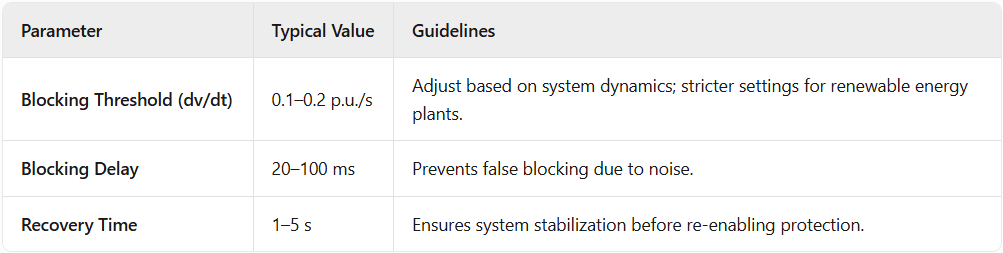
          ​If ∣dV/dt∣ exceeds the setting (e.g., ​0.1–0.2 p.u./s), the system identifies an abnormal transient and triggers blocking.

​Protection Blocking:​​
          ​Blocks affected protection functions (e.g., undervoltage protection) and logs the event.

​Recovery Mechanism:​​
          ​Automatically releases the blocking after the voltage change rate remains below the threshold for a set duration (e.g., ​1–5 seconds).

4.Voltage Rate-of-Change Blocking​ Key Parameters and Setting Recommendations

5.Conclusion​

          Voltage rate-of-change blocking is a critical logic in power system protection, identifying transient disturbances by monitoring ​dv/dt​ and intelligently blocking protection to prevent misoperation. It is essential for short-circuit events, capacitor switching, and other transient scenarios. Optimal performance requires ​careful threshold and delay settings​ to balance sensitivity and reliability.

Product recommendations More
GWZC-9000 Low-voltage load shedding panel
detail
GWZC-9551 VT (Voltage Transformer) Protection Relay
detail
GWZC-9581 Low-voltage generator protection relay
detail
GWZC-9694 Low-Frequency Low-Voltage Load Shedding Device
detail
GWZC-9506 Cable insulation monitoring device (IMD)​​(ANSI 64)
detail
Technical More
Voltage Rate-of-Change Blocking
Voltage Rate-of-Change Blocking (dv/dt Blocking): Functions, Features, and Working Principle​
Voltage rate-of-change blocking monitors dv/dt to prevent protection maloperation during transients like faults or capacitor switching, enhancing grid reliability
2025/07/15
Ground Distance Protection (21G)
Differences Between Phase-to-Phase Distance Protection (21P) and Ground Distance Protection (21G)
The core difference between phase-to-phase distance protection and ground distance protection lies in the selection of measured quantities, fault response range, and connection methods. They complement each other to form a complete distance protection system for high-voltage transmission lines, both following the basic principle: operation if the measured impedance is less than the setting impedance.
2026/03/04
Generator Protection Panel
Generator Protection Relay Panel : Composition and Function
Integrating protection, measurement, and communication, the Generator Protection Relay Panel can realize the protection and control of various units, enabling unattended or minimally attended operation. It can achieve generator differential protection, rotor earth fault protection, stator earth fault protection, excitation protection, overcurrent protection, overvoltage protection, overload protection, backup protection, etc.
2025/11/25
Transformer Protection Relay Panel
Transformer Protection Relay Panel:Composition and Function
Transformer Protection Relay Panel is primarily used in automation systems for substations and distribution stations in power systems of 11kV, 33kV, 132kV and above. Its main function is to ensure that the transformer can promptly trip the faulty circuit in case of overload, short circuit, gas relay activation, and other abnormal operating conditions, thereby protecting the main transformer from damage and preventing the expansion of faults.
2025/11/24
Inquiry Consultation
+86-17621210051
+86-17621210051
+86-17621210051
+86-17621210051
home product email
live chat
my