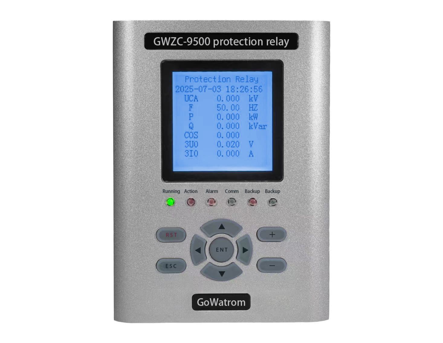
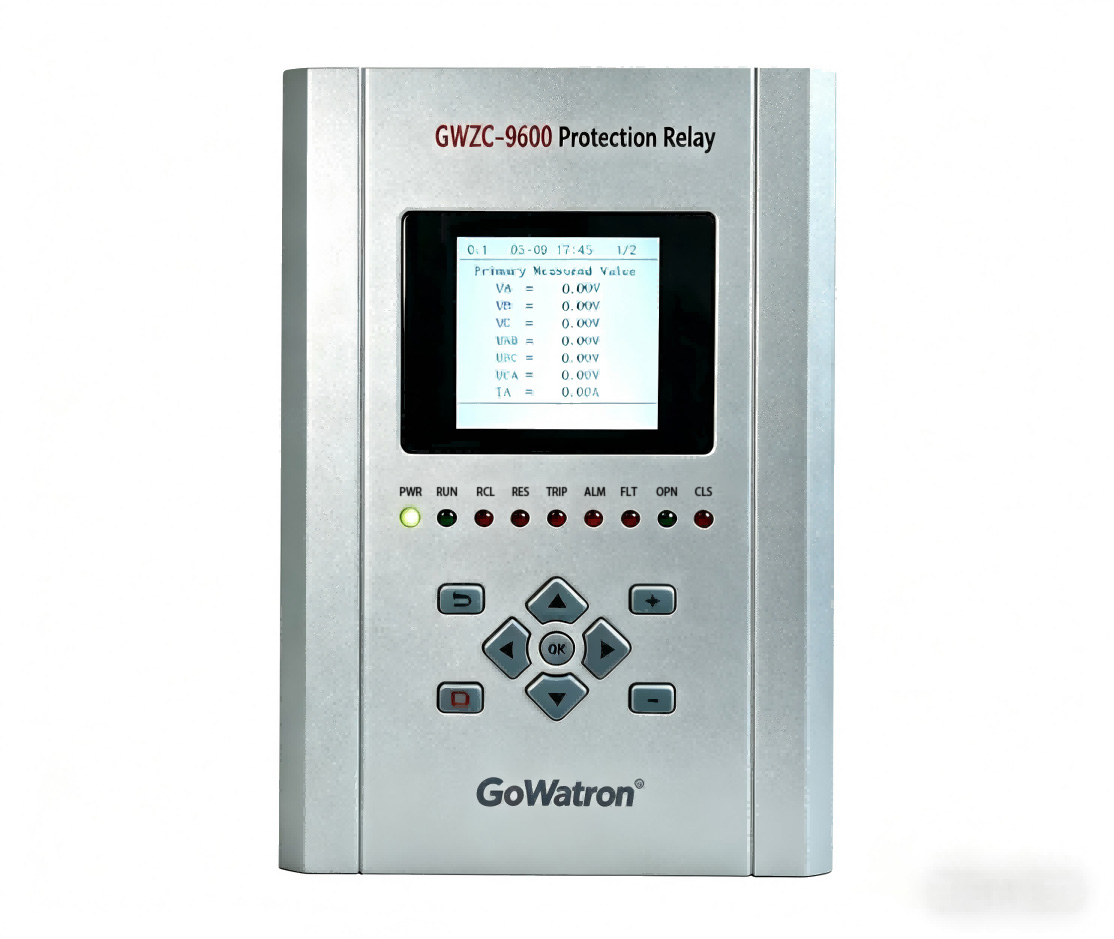
Three-Step Current Protection: Introduction, Functions, and Working Principles
Three-Step Current Protection is a classic protection relay scheme widely implemented in power systems for safeguarding transmission lines and electrical equipment. This protection relay configuration consists of three distinct stages: Instantaneous Overcurrent Protection (Stage I), Time-Limited Overcurrent Protection (Stage II), and Definite-Time Overcurrent Protection (Stage III). The protection relay’s core functionality lies in its graded coordination capability, which optimally balances speed, selectivity, and backup protection functions. As a critical protection relay solution, it has become essential for modern power distribution and transmission networks, offering reliable fault detection and clearance.
Introduction to Three-Step Current Protection
Three-Step Current Protection is a hierarchical protection method that ensures fast fault clearance while maintaining system stability. It is commonly applied in:
Transmission line protection
Transformer backup protection
Distribution system feeder protection
Role of Three-Step Current Protection
Instantaneous Fault Clearing (Stage I)
Trips without delay for severe short-circuits near the protection point (covers 80-90% of the line).
Selective Mid-Section Protection (Stage II)
Operates with a short time delay (0.3-0.5s) to clear faults in the remaining line section.
Backup Protection & Remote Fault Coverage (Stage III)
Acts as a backup for Stages I & II, with a longer delay (1-5s) to cover end-of-line and adjacent line faults.
Functions of Three-Step Current Protection
Step-Wise Protection
Uses current thresholds and time delays to isolate faults selectively.
Balanced Speed & Selectivity
Stage I prioritizes speed, while Stages II & III ensure selectivity via time grading.
Backup Protection
Stage III provides redundancy if primary protection fails.
Working Principle of Three-Step Current Protection
Stage I: Instantaneous Overcurrent Protection
Criterion: I>I set1 (set above max fault current at line end).
Operation Time: Near 0 seconds.
Coverage: Protects 80-90% of the line.
Stage II: Time-Limited Overcurrent Protection
Criterion: I>I set2 (coordinated with Stage I).
Time Delay: 0.3-0.5s to avoid overreach.
Stage III: Definite-Time Overcurrent Protection
Criterion: I>I set3 (set above max load current).
Time Delay: 1-5s, acting as backup for full line & adjacent sections.
Key Technologies & Setting Principles
Current Setting Rules
Stage I: I set1 =K rel ×I k.max (Reliability factor K rel =1.2−1.3).
Stage II: I set2 =K co ×I set1 (Coordination factorK co =1.1−1.2).
Stage III: Based on max load current & sensitivity verification.
Time Grading
Minimum 0.3s delay difference between stages to prevent misoperation.
Applications of Three-Step Current Protection
Transmission Line Protection (Often combined with distance protection).
Distribution Systems (Feeder & bus-section protection).
Motor & Transformer Backup Protection.