Back to smartelemfg Home
Contact us Merchants settle in
Back to smartelemfg Home
Home -Technical

Synchronism Check Function vs. Synchronizing Function: Roles, Differences, and Applications

Source: Maxwell He 2025-08-11 17:47:49

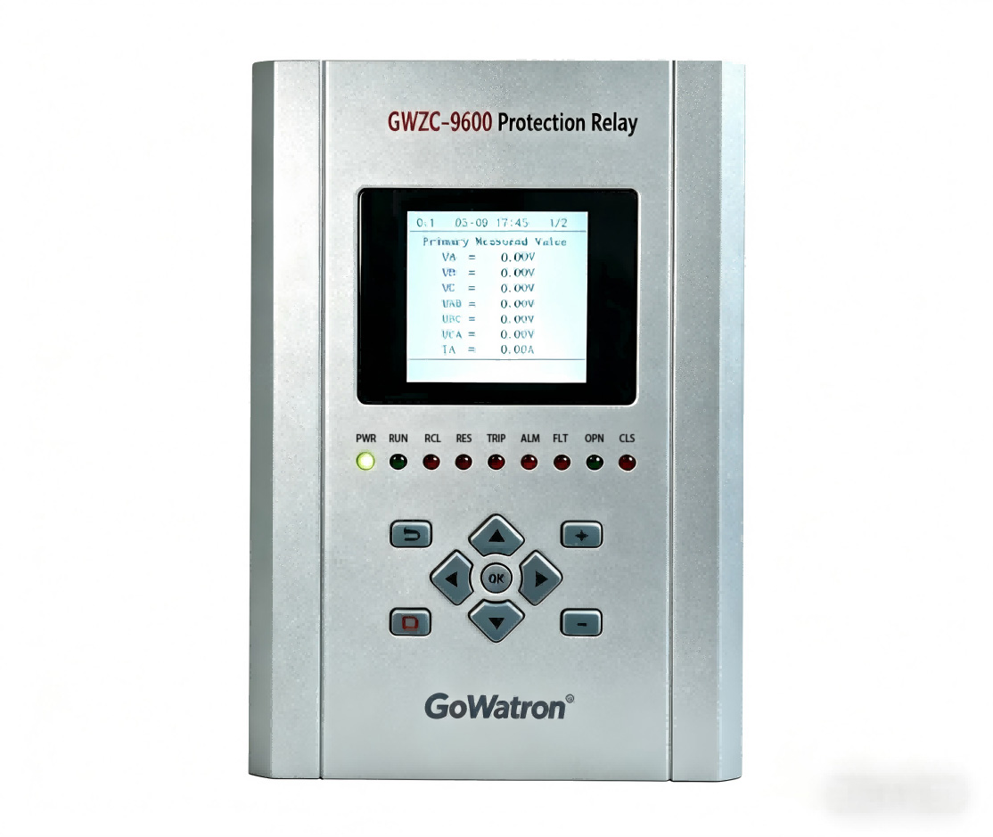
​1. Introduction to Synchronism Check Function in Line Protection relays​

          The ​synchronism check function​ (coded SYN or 25) is a safety interlock that prevents circuit breaker closing during unsynchronized conditions. It blocks closing commands when voltage difference (ΔU), frequency difference (Δf), or phase-angle difference (Δθ) exceed thresholds, thereby avoiding high inrush currents and power oscillations. Its ​core objective​ is to validate electrical synchronization between two sources (e.g., busbar and line/generator sides) before permitting manual/automatic closing.

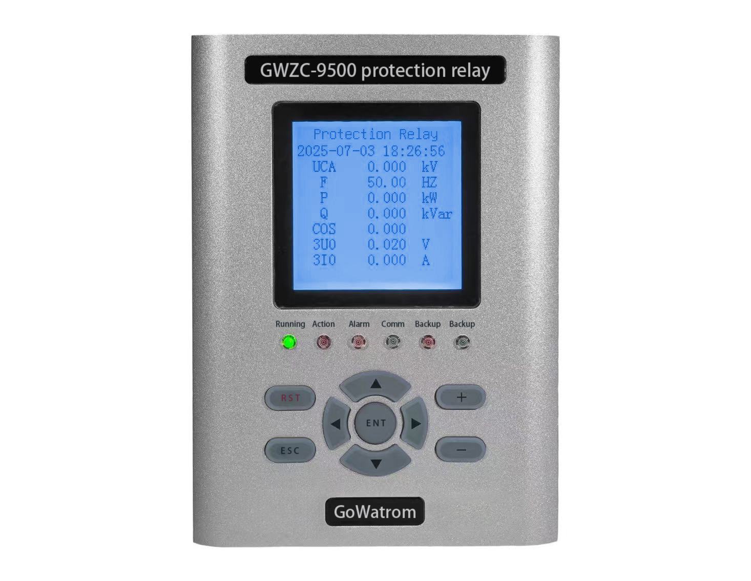
​2. Introduction to Synchronizing Function in Synchronizing relays​
          The ​synchronizing function​ in auto-synchronizing relays enables smooth interconnection of independent power sources. As a closed-loop control system, it achieves near-zero deviations (ΔU ≈ 0%, Δf ≈ 0 Hz, Δθ ≈ 0°) through real-time monitoring, dynamic parameter adjustments, and predictive closing. Its ​core value​ lies in active regulation and sub-second timing control.

​3. Application Scenarios of Line Protection Synchronism Check​

  • ​Manual Closing/Interconnection: Validates synchronization before human-initiated breaker closure.
  • ​Auto-Reclosing: Enables reclosing only if sources synchronize after a fault trip.
  • ​Bus Transfer Schemes: Checks synchronicity for automatic transfer to standby sources.
  • ​Generator Synchronization (Backup)​: Secondary verification in simple systems.

​4. Application Scenarios of Synchronizing relays​
The ​synchronizing function​ specializes in precision-critical tasks:

  • ​Generator Synchronization: Essential for fossil/nuclear/hydro units.
  • ​Black Start Restoration: Rebuilds de-energized networks.
  • ​Tie-Line Interconnection: Enables stable regional grid interlinks.

​5. Working Principles: Line Protection Synchronism Check​

  • ​Measurement: Monitors voltages (Ubus, Uline) via PTs.
  • ​Calculation: Computes real-time ΔU, Δf, and Δθ.
  • ​Prediction: Estimates Δθclose at future contact closure:
    Δθclose = Δθnow + ωs × tclose
  • ​Interlock Logic:
    Enables closing if Δθclose, ΔU, Δf within limits.
    Blocks closing + alarms on deviation.

​6. Working Principles: Synchronizing relays​

  • ​Startup: Verifies voltage validity & receives sync command.
  • ​Parameter Regulation​ (key differentiator):
    ​Coarse Adjustment: Reduces Δf < 0.3 Hz, ΔU < 5%.
    ​Fine Tuning: Optimizes to Δf < 0.1 Hz, ΔU < 1%.
  • ​Closing Timing:
    Calculates slip angular velocity (ωs) and Δθclose.
    Issues closing pulse when Δθclose enters window (e.g., |±2°|).
  • ​Post-Closing Check: Confirms successful interconnection.

​7. Key Differences Between the Two Functions​
​Line Protection relay Synchronism Check:

  • Role: Safety gatekeeper (“Can we close?”)
  • Action: Passive verification
  • Precision: Tolerates Δθ < 20°
  • Actuation: Enables external closing circuits
  • Primary Use: Transmission auto-reclosing & manual switching

​Synchronizing Device Function:

  • Role: Active interconnector (“Achieve perfection & close”)
  • Action: Closed-loop voltage/frequency/phase regulation
  • Precision: Targets Δθ < 2°
  • Actuation: Directly issues closing commands
  • Primary Use: Generator synchronization & tie-line paralleling

​Conclusion​
          The ​synchronism check​ in line protection relay provides vital safety interlocks during routine grid operations. Conversely, the ​synchronizing function​ in dedicated equipment enables mission-critical generator/tie-line interconnections through closed-loop control. While synchronism checks prevent catastrophic errors, synchronizing relay achieve near-perfect synchronization via active parameter regulation and predictive algorithms.

Product recommendations More
GWZC-9811 Line protection relay
detail
GWZC-9611 Feeder Protection Relay
detail
GWZC-9000 Sewage Treatment Automation Control System
detail
GWZC-9000 Drainage Pumping Station Automation System
detail
GWZC-9802 Directional Earth Fault Relay (DEF Relay)
detail
Technical More
Automatic Transfer Switch (ATS) Side View
What is Parallel Operation
​Parallel operation​ involves connecting two or more independent AC power sources (e.g., generators, grids) to share electrical loads seamlessly. This process—synchronization—demands precise matching of voltage magnitude, frequency, and phase angles between systems before interconnection. Critical for grid expansion, backup power, and renewable integration, it enables redundant supply during failures.
2025/08/15
Generator-Transformer Differential Protection Relay Rear View
Ring-Closing Operation: Definition & Importance in Power Grids
A ring-closing operation involves closing a normally open switch within a closed-loop electrical network fed by a single power source. This creates parallel paths to redistribute loads without interruption, primarily for maintenance or network reconfiguration. Key prerequisites are voltage difference under 5%, phase angle alignment below 5 degrees, and pre-calculation of induced circulating currents to avoid equipment damage. Distinct from connecting independent systems, this procedure requires advanced monitoring but avoids synchronization complexity. Strict protocols using real-time sensors and simulations ensure safe execution, making it fundamental for resilient distribution networks like ring-main units (RMUs) in urban grids.
2025/08/14
Main Transformer On-load Tap Changer Control Relay Side View
Transformer Protection Configuration Principles
Transformer protection is critical for maintaining power system reliability. A well-designed ​transformer protection configuration​ must balance speed, selectivity, and sensitivity to prevent equipment damage and outages. ​Primary protection​ (e.g., differential and gas protection) acts instantly for internal faults, while ​backup protection​ (e.g., overcurrent, zero-sequence) provides redundancy for extended coverage. This guide covers key principles, settings, and coordination to optimize ​transformer protection​ schemes for different transformer types and voltage levels.
2025/08/11
Generator-Transformer Differential Protection Relay Rear View
What Are Positive Sequence, Negative Sequence, and Zero Sequence in Three-Phase Circuits?
In relay protection systems, we often encounter concepts such as zero-sequence current protection in microprocessor-based protection devices and inverse-time negative-sequence protection in transformer protection devices. Initially, I found these concepts quite confusing. However, to facilitate subsequent study and work, it is essential to understand these critical concepts of positive sequence, negative sequence, and zero sequence in three-phase circuits.
2025/08/08
Inquiry Consultation
+86-17621210051
+86-17621210051
+86-17621210051
+86-17621210051
home product email
live chat
my