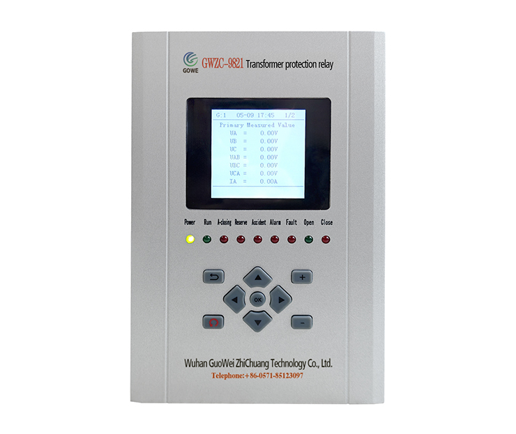
The configuration schemes for busbar arc flash protection and feeder arc flash protection are critical components in the protection of medium and low-voltage switchgear, aiming to quickly clear the severe hazards caused by internal arc faults (arc flash). Below is a detailed, professional, and actionable configuration scheme provided for you.
I. Core Principles and Objectives of Arc Flash Protection
- Safety First: Arc flash faults generate immense energy (high temperature, high pressure, intense light). The primary objective is to protect personnel and equipment safety.
- Speed: Protection operation must be completed within an extremely short time (typically requiring < 7ms detection + relay operation time, total time ≤ 100ms) to limit arc energy.
- Selectivity: The protection operation should be selective, meaning it only clears the faulty component to avoid widespread power outages. Busbar protection should operate the main busbar breaker, and feeder protection should operate the corresponding feeder breaker.
- Reliability: The system should effectively distinguish between internal and external faults to avoid maloperation and failure to operate.
II. Composition of an Arc Flash Protection System
A complete arc flash protection system typically consists of three parts:
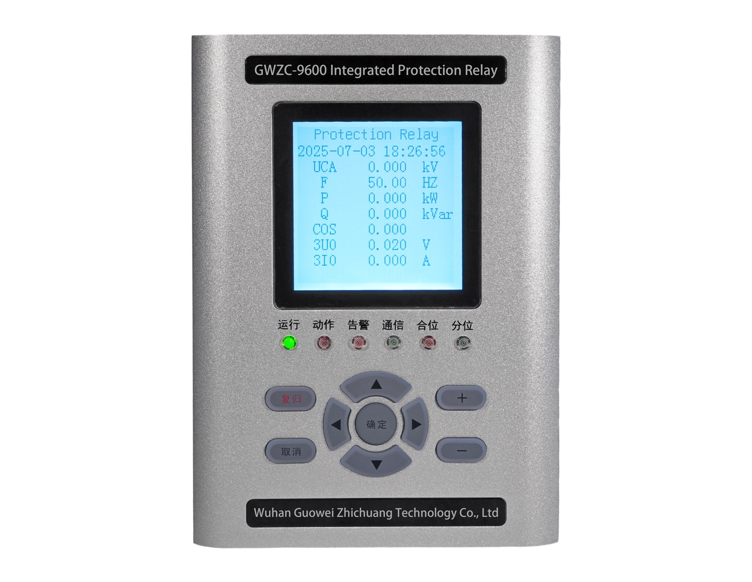
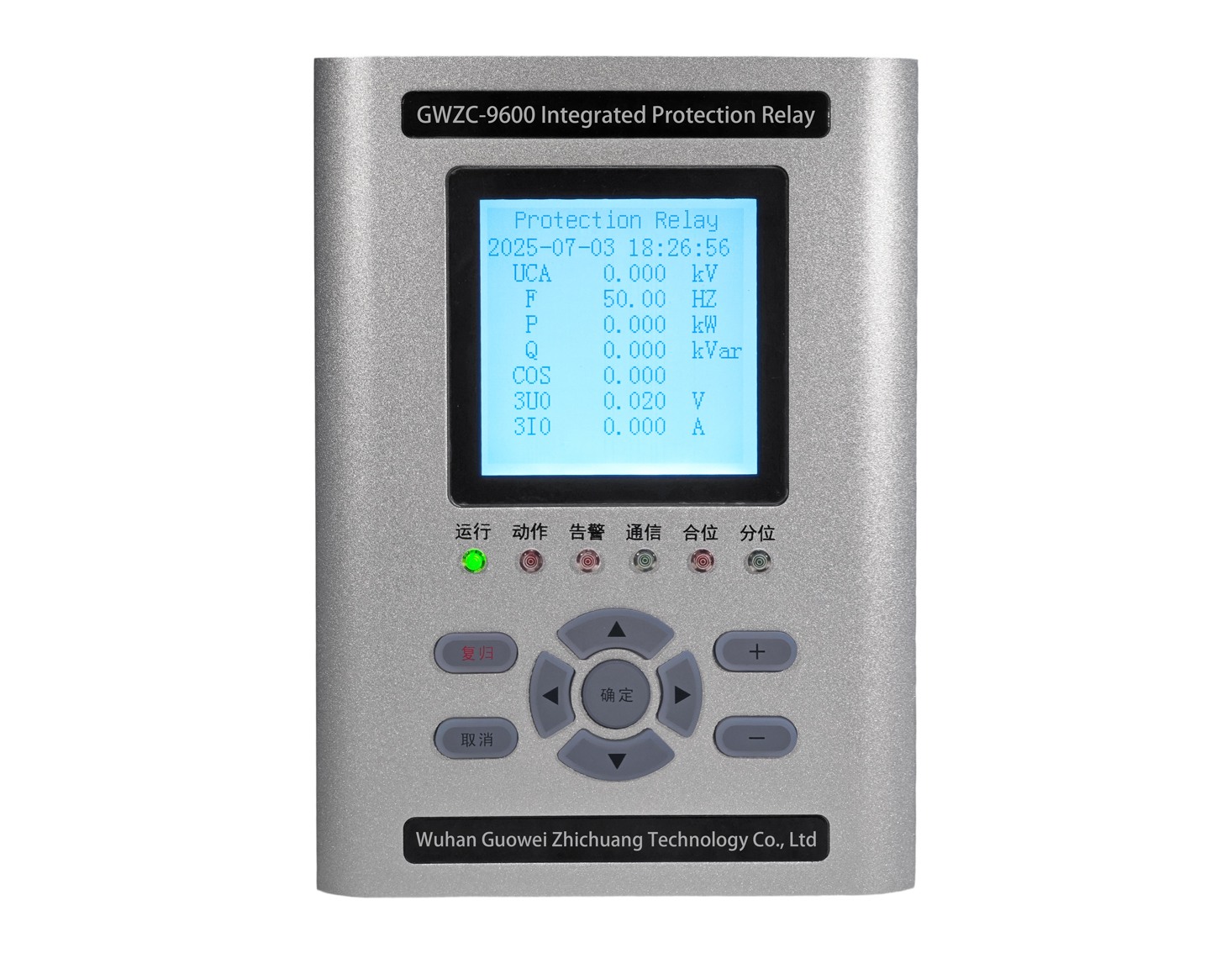
- Arc Flash Protection Relay: The “brain” of the system, responsible for receiving and processing signals, performing logical judgments, and issuing trip commands.
- Arc Flash Sensors (Probes): Installed in various compartments of the switchgear (e.g., busbar compartment, circuit breaker compartment, cable compartment, etc.) to detect arc flash signals of specific wavelengths. There are mainly two types: point sensors and fiber optic sensors.
- Current Detection Unit: Typically utilizes the current signal provided by existing Current Transformers (CTs). The dual-criterion principle of “Arc Flash + Current” is key to improving reliability and preventing maloperation.
III. Detailed Arc Flash Protection Configuration Schemes
Scheme 1: Busbar Arc Flash Protection Configuration
- Protected Object: All incoming lines, bus ties, capacitors, and other main breakers on a busbar section.
- Sensor Placement:
- Install arc flash sensors inside each busbar compartment requiring protection (e.g., A/B/C three-phase busbar compartments).
- Point sensors are commonly used, installed directly on the top or sidewall of the compartment to cover the entire space.
- Alternatively, fiber optic sensors can be used, arranged in a loop within the compartment for dead-angle-free detection.
- Logic Configuration (Recommended Dual-Criterion):
- Criterion 1 (Initiation Criterion): Busbar CT current > setting value Iset (usually set to 1.2~1.5 times the rated current to avoid disturbances during normal operation).
- Criterion 2 (Operation Criterion): The arc flash sensor in the corresponding busbar compartment detects an arc flash signal.
- Operation Logic: “AND” logic. The main control unit (judges as) an internal busbar arc flash fault only when both conditions of “fault current present” and “arc flash signal present” are met simultaneously.
- Operation Output: Instantly trip the incoming breaker and bus tie breaker on the busbar to isolate the fault. Simultaneously send a signal and alarm to the superior system.
- Advantages:
-
- The dual-criterion significantly reduces the risk of maloperation due to sensor false induction (e.g., from lighting, maintenance flashlights).
- Fast operation effectively protects the busbar and connected equipment.
Scheme 2: Feeder Arc Flash Protection Configuration
- Protected Object: A single outgoing circuit (feeder).
- Sensor Placement:
- Install arc flash sensors in the circuit breaker compartment and cable compartment of each feeder circuit (typically 1-2 per compartment per cabinet).
- Point sensors are a common choice; the installation position should aim at locations where an arc is likely to occur (e.g., near breaker contacts, cable connections).
- Logic Configuration:
- Criterion 1: The CT current of this feeder circuit > setting value Iset (can be set to the minimum operating current for higher sensitivity).
- Criterion 2: The arc flash sensor inside this feeder cabinet detects an arc flash signal.
- Operation Logic: Also uses “AND” logic.
- Operation Output: Instantly trip the circuit breaker for this feeder circuit. Only the faulty circuit is cleared, without affecting the normal operation of the busbar and other feeders.
- Advantages:
- High selectivity, minimizing the scope of fault impact.
- Works in coordination with busbar protection to form a complete, selective hierarchical protection system.
IV. Overall System Architecture and Coordination Scheme
In a typical substation, busbar arc flash protection and feeder arc flash protection do not work in isolation but cooperate.
Recommended Architecture: Hierarchical Distributed System
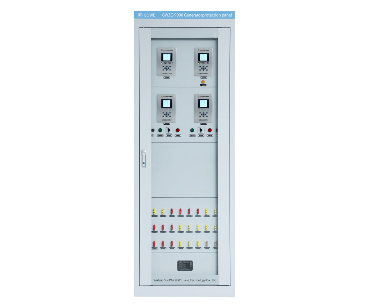
- Configure one main control unit, centrally located in the main control room or near the switchgear group.
- All arc flash sensors are installed in various compartments of each switchgear.
- All CT current signals are fed to the main control unit via hard wiring or communication.
- Configure protection logic and settings individually within the main control unit for each unit requiring protection (each busbar section, each feeder cabinet).
Arc Flash Protection Operation Coordination Process:
- If a fault occurs in a feeder cabinet, the “arc flash + current” criterion for that cabinet is met. The feeder arc flash protection relay trips only that feeder breaker. The busbar arc flash protection relay does not operate.
- If a fault occurs in the busbar compartment, the “arc flash + current” criterion for busbar protection is met. The main control unit trips the incoming breaker and bus tie breaker. The feeder arc flash protection relays do not operate.
- If the main control unit detects arc flash signals from multiple feeder cabinets and the busbar simultaneously, it prioritizes and judges as a busbar fault and trips the incoming breaker.
V. Key Configuration and Setting Recommendations for Arc Flash Protection
- Sensor Selection and Installation:
- Point Sensors: Simple installation, low cost, require reasonable planning of quantity to ensure coverage.
- Fiber Optic Sensors: Large detection range, no dead angles, but slightly more complex installation and higher cost.
- Absolutely avoid pointing sensors directly at the cabinet door viewing window, lighting, or other light sources.
- Current Setting:
- Feeder Circuit: Iset should be greater than the load current but less than the minimum fault current. Typically can be set to > 1.2 I_load (load current).
- Busbar Circuit: Iset should be set above the maximum load current and the current flowing through the busbar during a feeder fault, usually set to > 1.3 I_max (maximum load current).
- Time Setting:
- Arc flash protection generally operates instantaneously, without time delay.
- Ensure the inherent opening time of the relay and breaker itself is sufficiently short (total operation time ≤ 100ms).
- Testing and Maintenance:
- A functional test must be performed before system commissioning, simulating an arc flash signal (using a dedicated test lamp) to verify the correctness of the sensors, logic, and trip circuit.
- Conduct regular inspections to check if sensors are obstructed or contaminated.
Summary of Arc Flash Protection Configuration Scheme
The core of an excellent arc flash protection configuration scheme is:
- “Dual-Criterion” Principle: Firmly adopt “Arc Flash + Current” to improve reliability.
- Layered and Zoned Layout: Clearly distinguish the scope of busbar protection and feeder protection.
- Selective Tripping: Ensure the fault is isolated to the greatest extent possible.
- Speed: Select high-performance equipment to ensure the total operation time meets requirements.

