Back to smartelemfg Home
Contact us Merchants settle in
Back to smartelemfg Home
Home -Technical

Ring-Closing Operation: Definition & Importance in Power Grids

Source: Maxwell He 2025-08-14 16:47:24

Essentials of Ring-Closing: Seamless Load Switching in Loop Networks

          In electrical power systems, a ​ring-closing operation​ refers to the controlled closure of a normally open switch or breaker within a closed-loop network topology. Unlike interconnecting independent grids (synchronization), this technique operates exclusively within a single, strongly coupled system—such as feeders from the same substation or tightly bonded grid sections.

          Its primary purpose is to enable seamless ​load transfer​ during maintenance, fault recovery, or network reconfiguration without interrupting supply. For example, closing a tie switch between two parallel 10kV lines allows shifting loads from Line A (to be de-energized) to Line B. Critical technical prerequisites include validating ​negligible voltage difference​ (ΔU <5%), ​phase angle alignment​ (<5°), and pre-calculation of induced ​circulating currents​ to ensure thermal/mechanical safety. Modern grids use dedicated protection schemes and IoT sensors for real-time monitoring.

          While distinct from high-risk synchronization (parallel operation) between asynchronous systems, improper ring-closing can still cause Protection relay maloperation or equipment stress. Thus, utilities mandate rigorous simulation studies and standardized switching protocols under N-1 contingency criteria.

1. Ring-Closing Operation:Definition & Context​

          A ring-closing operation involves closing a disconnection point (e.g., switch, circuit breaker) in an electrically closed-loop network fed by a ​single power source​ or tightly coupled sources. This converts radial feeders into parallel paths, redistributing loads while maintaining grid integrity.

​2.Ring-Closing Operation: Operational Workflow​

​Pre-Condition Checks:

  • Voltage difference < 5% at closing point.
  • Phase angle deviation ≤ 5°.
  • Circulating current calculation (must not exceed equipment ratings).

​Action Sequence:

  • Close tie switch/circuit breaker.
  • Monitor transient currents.
  • Transfer loads by opening the original feeder.

​Safety Mechanisms:

  • Differential protection.
  • Overcurrent relays with directional logic.

​3.Ring-Closing Operation: Applications​

  • ​Load Transfer: Hot-switching circuits during maintenance (e.g., substation upgrades).
  • ​Fault Management: Isolating faulted sections while restoring supply via alternative paths.
  • ​Loss Reduction: Optimizing power flow to minimize resistive losses in congested feeders.

​4. Ring-Closing Operation:Technical Challenges​

  • Circulating Currents: Result from voltage imbalances, potentially overheating cables/transformers.
  • ​Protection Coordination: Risk of relay misoperation due to altered fault-current paths.
  • ​Grid Stability: Voltage fluctuations during transition, requiring reactive power support.

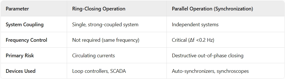
​5. Ring-Closing Operation:Comparison with Parallel Operation

6. Ring-Closing Operation:Safety Protocols​

  • ​Mandatory Simulations: EMT/PSCAD modeling to predict dynamic behavior.
  • ​Grid Code Compliance: Adherence to IEC 61970/IEEE 1547 for interoperability.
  • ​Live Testing: Phasor measurement units (PMUs) for real-time angle verification.

7. Ring-Closing Operation:Industry Use Cases​

  • ​Urban Distribution: Ring-main units (RMUs) in cities for N-1 redundancy.
  • ​Renewable Integration: Seamless switching between hybrid sources (solar/wind/grid).
  • ​Microgrids: Reconfiguring islanded/localized networks without synchronization.
Product recommendations More
GWZC-9000 Sewage Treatment Automation Control System
detail
GWZC-9000 Drainage Pumping Station Automation System
detail
GWZC-9802 Directional Earth Fault Relay (DEF Relay)
detail
GWZC-9000 Integrated Automation System for Photovoltaic Power Plants
detail
GWZC-9000 Hydropower Plant Automation System
detail
Technical More
Automatic Transfer Switch (ATS) Side View
What is Parallel Operation
​Parallel operation​ involves connecting two or more independent AC power sources (e.g., generators, grids) to share electrical loads seamlessly. This process—synchronization—demands precise matching of voltage magnitude, frequency, and phase angles between systems before interconnection. Critical for grid expansion, backup power, and renewable integration, it enables redundant supply during failures.
2025/08/15
Synchronism Check Function vs. Synchronizing Function: Roles, Differences, and Applications
This article compares the ​synchronism check function​ in line protection devices and the ​synchronizing function​ in dedicated synchronizing equipment. The ​synchronism check function​ serves as a safety interlock for circuit breaker closing operations, while the ​synchronizing function​ enables precise generator synchronization and critical tie-line interconnections with active parameter regulation. Explore core principles, application scenarios, and technical distinctions between these critical power system components.
2025/08/11
Main Transformer On-load Tap Changer Control Relay Side View
Transformer Protection Configuration Principles
Transformer protection is critical for maintaining power system reliability. A well-designed ​transformer protection configuration​ must balance speed, selectivity, and sensitivity to prevent equipment damage and outages. ​Primary protection​ (e.g., differential and gas protection) acts instantly for internal faults, while ​backup protection​ (e.g., overcurrent, zero-sequence) provides redundancy for extended coverage. This guide covers key principles, settings, and coordination to optimize ​transformer protection​ schemes for different transformer types and voltage levels.
2025/08/11
Generator-Transformer Differential Protection Relay Rear View
What Are Positive Sequence, Negative Sequence, and Zero Sequence in Three-Phase Circuits?
In relay protection systems, we often encounter concepts such as zero-sequence current protection in microprocessor-based protection devices and inverse-time negative-sequence protection in transformer protection devices. Initially, I found these concepts quite confusing. However, to facilitate subsequent study and work, it is essential to understand these critical concepts of positive sequence, negative sequence, and zero sequence in three-phase circuits.
2025/08/08
Inquiry Consultation
+86-17621210051
+86-17621210051
+86-17621210051
+86-17621210051
home product email
live chat
my