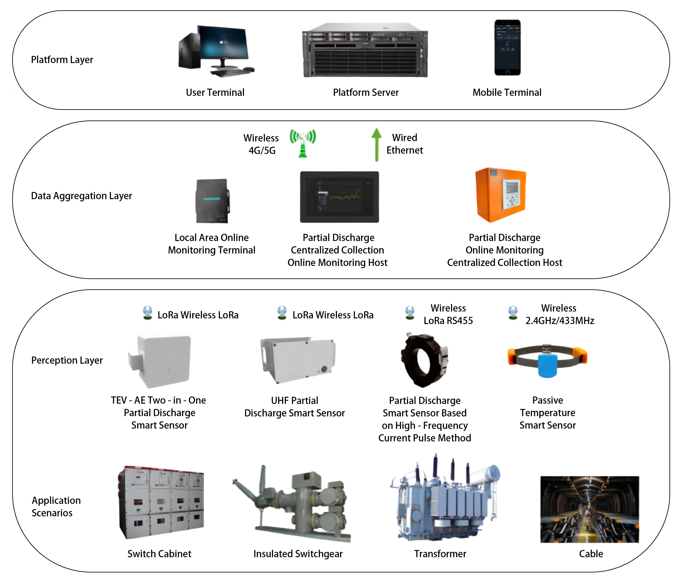
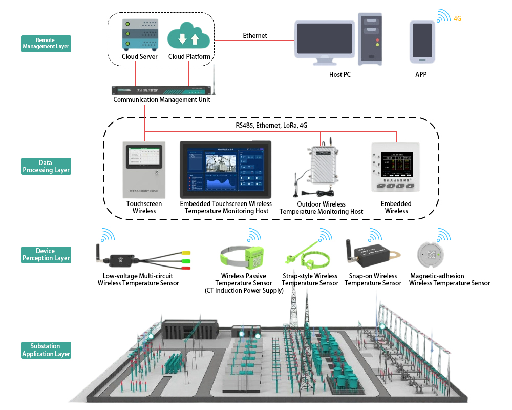
The protection relay tripping circuit refers to the critical electrical control loop that executes trip/close commands from protective relays to circuit breakers, ensuring rapid fault isolation in power systems. This system integrates protection logic with breaker control functions.
1. Essential Components of Protection Relay Tripping Circuit
- Trip Coil Loop: The primary path where relay contacts energize the breaker’s trip coil upon fault detection
- Closing Circuit: Dedicated loop for postfault restoration via close coil/motor operation
- Auxiliary Control Elements: Including sealin relays, antipumping modules, position switches, and interlock contacts
- Signal Feedback Paths: Breaker status indicators and SCADA communication interfaces
2. Operational Mechanism of Protection Relay Tripping Circuit
Standard Trip Sequence:
- Fault Initiation → Protection relay (e.g., 50/51 overcurrent unit) detects abnormality
- Contact Closure → Relay output contacts complete DC control circuit (typically 110/220VDC)
- Energy Transfer → Current flows through:
▪ Relay contacts → ▪ Breaker auxiliary contacts (52a) → ▪ Trip coil → ▪ Return path
- Mechanical Action → Trip coil activates breaker mechanism within specified time (e.g., <30ms)
- System Feedback → Auxiliary contacts update status to local/remote monitoring systems
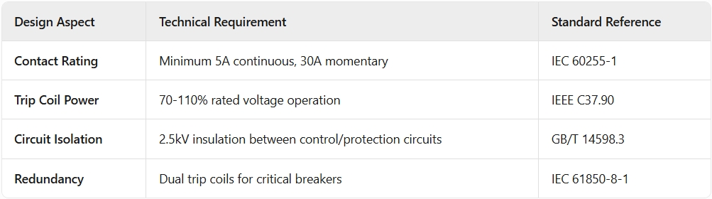
3. Critical Design Standards for Protection Relay Tripping Circuit
4. Advanced Applications of Protection Relay Tripping Circuit
- HighSpeed Tripping: <15ms operation for generator differential protection (87G)
- Synchrocheck Closing: Integrated voltage/phase angle verification (25 function)
- Cascaded Tripping: Zoneselective interlocking between multiple relays
- Arc Flash Mitigation: Light detection (32L) triggering instantaneous trip
5. Commissioning & Maintenance of Protection Relay Tripping Circuit
Field Test Procedures:
- Contact Resistance → Measure <0.1Ω across all critical junctions
- Trip Coil Current → Verify inrush (typically 515A) vs hold current (0.52A)
- Timing Validation → Confirm total trip time < manufacturer specification
- Insulation Test → 1000V megger test for 1 minute minimum
Common Failure Modes:
- Coil burnout due to prolonged energization
- Contact welding from excessive current
- False trips from ground loops or EMI