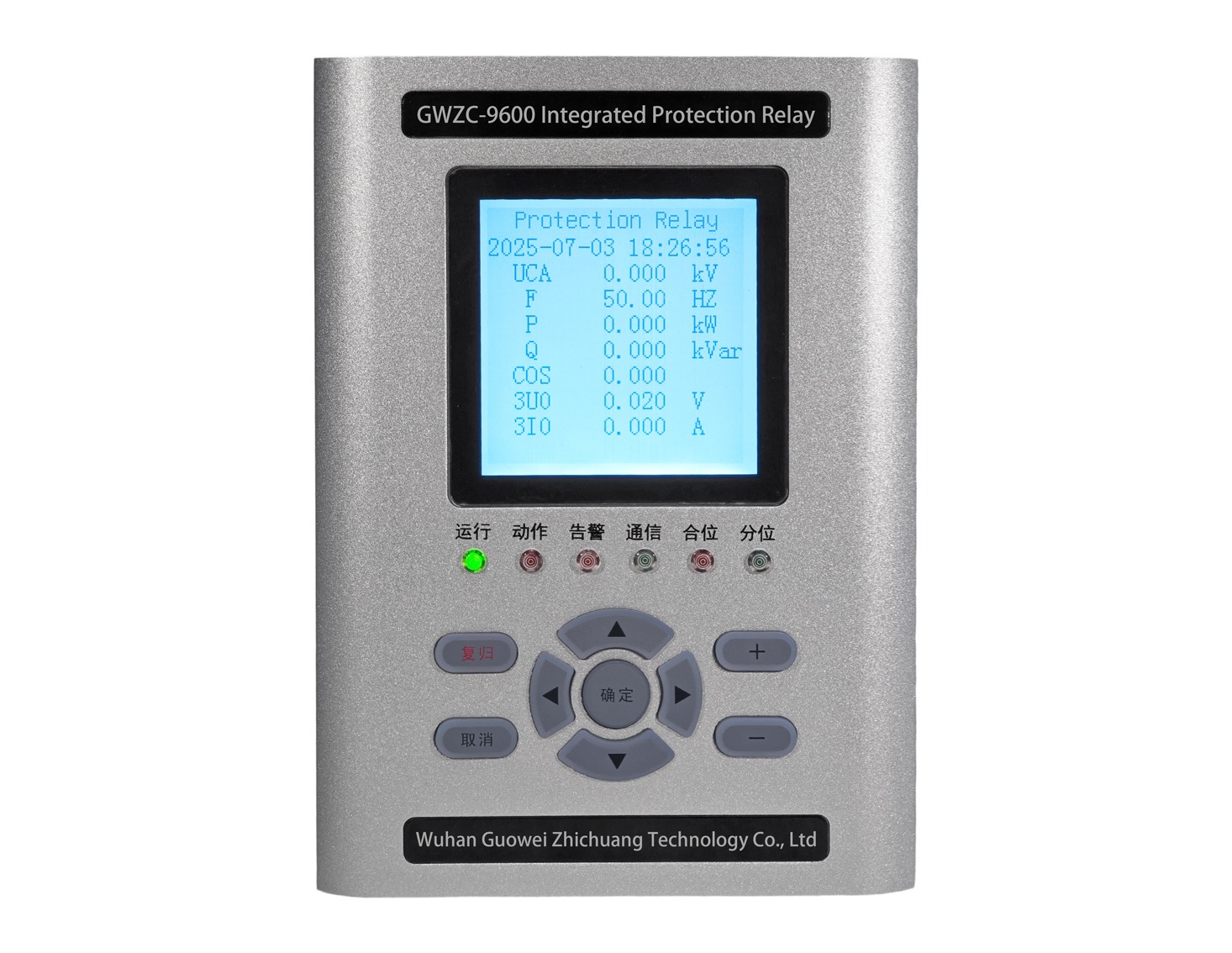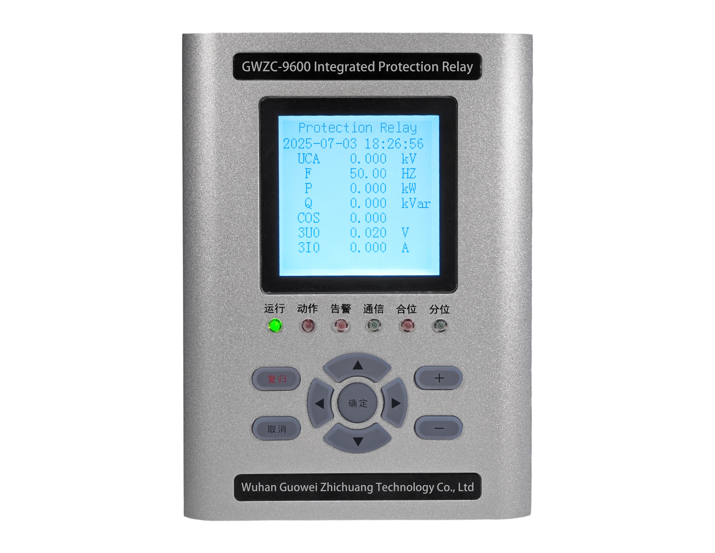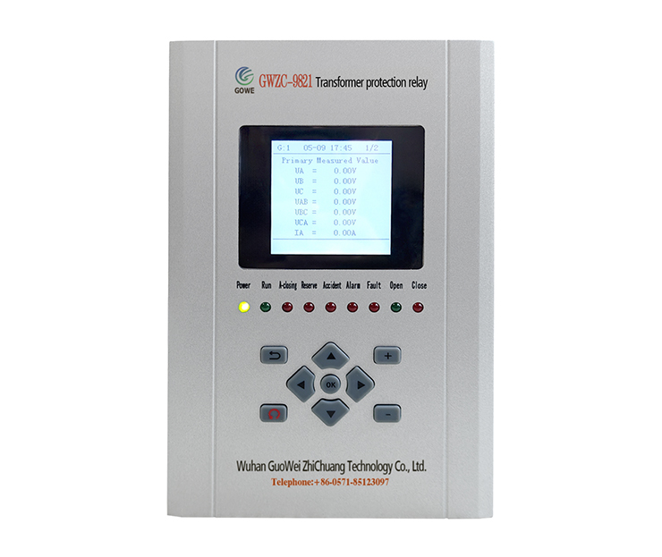
Introduction to Motor LockedRotor Protection
Motor lockedrotor protection is a safety mechanism designed to prevent motor damage caused by overheating due to excessive load or mechanical jamming. When a motor is locked, the current surges dramatically, and without timely intervention, it can burn out windings or damage equipment. Motor protection relays monitor parameters such as current, temperature, or speed and quickly cut off power or trigger an alarm upon detecting a lockedrotor condition. This ensures safe motor operation, extends equipment lifespan, and minimizes downtime. It is widely used in applications like pumps, fans, and conveyors where sudden blockages may occur.
Function of Motor LockedRotor Protection
The primary role of lockedrotor protection is to prevent severe accidents caused by motor stalling due to mechanical obstruction, overload, or power supply issues. During a lock, current can spike to 57 times the rated value, rapidly generating excessive heat that may destroy insulation or melt windings. The protection device promptly interrupts the circuit, avoiding motor burnout, mechanical deformation, or cascading damage to connected systems. It enhances operational safety, reduces maintenance costs, and ensures reliability in critical applications such as industrial machinery and HVAC systems.
Features of Motor LockedRotor Protection
1. Current Monitoring: Detects realtime current to identify lockedrotor conditions (e.g., sudden current spikes).
2. Fast Tripping: Disconnects power or triggers an alarm within a set time.
3. Time Delay: Distinguishes between startup inrush current and actual lockedrotor current to prevent false trips.
4. Temperature Compensation: Combines thermal sensors for dual protection.
5. Fault Logging: Records lock events for diagnostics. Advanced models may include autoreset or remote alerts.
Working Principle of Motor LockedRotor Protection
Lockedrotor protection operates based on electrical and thermal changes during motor stalling, using the following detection methods:
1. Current Detection Principle
Overcurrent Criteria: Lockedrotor current exceeds the rated value (typically 38 times). Protection devices use current transformers (CTs) or Hall sensors to compare against preset thresholds.
Time Delay: A delay (e.g., 0.55 sec) prevents false triggering during motor startup.
2. Temperature Detection Principle
PTC/NTC Thermistors: Embedded in windings; resistance changes trigger protection when overheated.
Bimetallic Relays: Heatinduced deformation opens contacts to cut power.
3. Speed/BackEMF Detection
Encoders or Hall sensors monitor speed; if it drops below a threshold (e.g., 10% of rated speed) with sustained high current, a lock is confirmed. Brushless motors detect loss of backEMF.
4. Integrated Protection Solutions
Modern intelligent protectors (e.g., microcontrollerbased) combine:
CurrentTime Curve: Inversetime characteristics (faster tripping at higher currents).
Power Factor Monitoring: Lockedrotor conditions lower power factor.
Logic Analysis: Filters transient load fluctuations for accuracy.
