The main components of a hydropower plant integrated automation system are as follows:
1. Station Level / Control and Monitoring Level
This is the “brain” of the entire system, located in the central control room, responsible for plant-wide supervision, control, management, and communication.
Supervisory Control And Data Acquisition(SCADA System)
Full Name: Supervisory Control And Data Acquisition
Function: This is the core monitoring and control software, running on servers and workstations. It is responsible for:
Data Acquisition: Collecting all real-time data from lower-level devices (e.g., voltage, current, power, water level, temperature, switch status).
Data Processing and Calculation: Performing tasks like limit alarm checking, total power calculation, and energy summation.
HMI: Dynamically displaying the plant single-line diagram, equipment status, operational parameters, and alarm information graphically.
Control and Operation: Providing remote control functions for switches, circuit breakers, unit start/stop, etc.
Sequence of Events Recording and Post-Fault Analysis: Recording the precise sequence of event occurrences for incident analysis.
Historical Data Archiving: Storing long-term operational data for report generation and performance analysis.
Human-Machine Interface (HMI)
Full Name: Human-Machine Interface
Function: The graphical interface through which operators interact with the system, typically implemented via multiple high-performance workstations.
Historian / Database Server
Function: Stores all historical operational data, event records, operation logs, etc.
Engineering Workstation
Function: Used by engineers for system configuration, program modification, logic download, database maintenance, and troubleshooting.
Communication Gateway
Function: Responsible for communication with the higher-level dispatch center (e.g., grid control center), using standard telecontrol protocols such as IEC 60870-5-101/104 or DNP3.
GPS Time Synchronization Unit
Function: Provides a unified, precise time reference for the entire automation system, ensuring the comparability of event records from all devices.
2. Local Control Level / Bay Level
This is the “nerve center” of the system, distributed near major plant equipment, such as the generator floor and switchyard. These units can independently perform monitoring, control, and protection tasks for their respective bays, operating autonomously even if communication with the station level is lost. Core equipment includes:
Programmable Logic Controller (PLC)
Full Name: Programmable Logic Controller
Function: The core of local control, responsible for executing complex sequential logic, such as:
Unit LCU: Executing automatic start-up, shutdown, synchronization, and load regulation sequences for the hydro-generator unit.
Switchyard LCU: Controlling the opening and closing operations of circuit breakers and disconnectors.
Common Services LCU / Auxiliary Systems LCU: Controlling the station service power system, drainage system, compressed air system, technical water system, etc.
Local Control Unit (LCU)
Full Name: Local Control Unit
Function: An integrated concept that typically includes a PLC, I/O modules, protection relays, communication interfaces, etc., forming a complete local control node.
Intelligent Electronic Device (IED)
Full Name: Intelligent Electronic Device
Function: Refers to all microprocessor-based intelligent devices with communication capabilities, forming the foundational elements of the system. Mainly includes:
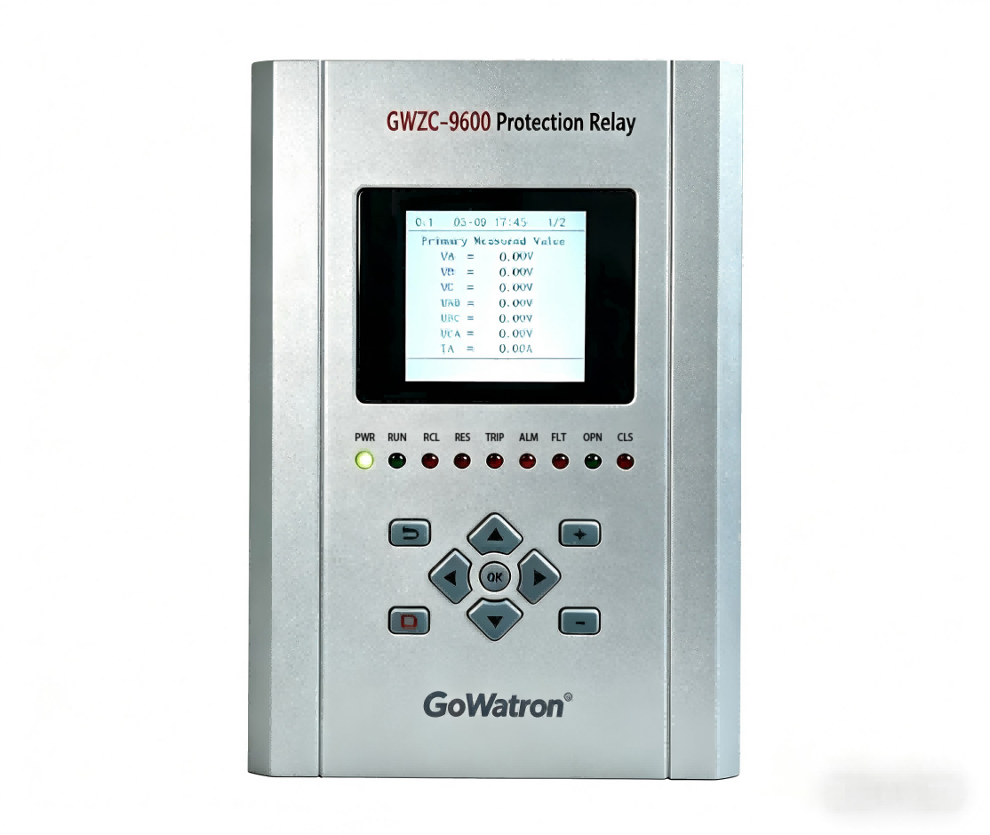
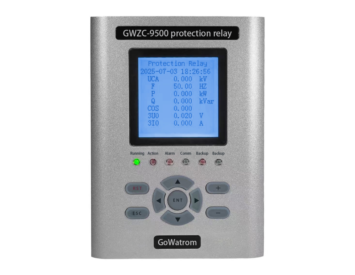
Protection Relays: Dedicated to detecting power system faults (e.g., overcurrent, differential, earth faults) and quickly isolating faulty equipment.
Measurement and Control Devices: Responsible for acquiring analog (voltage, current) and digital signals, and executing control commands.
Governor: Controls the turbine guide vane opening to regulate unit speed and active power.
Excitation System: Regulates the generator’s field current to control terminal voltage and reactive power.
Synchronizer / Automatic Synchronizer: Automatically checks synchronization conditions and issues a closing command when voltage, frequency, and phase angle match.
3. Process Level / Primary Equipment Level
This is the “senses and hands” of the system, consisting of primary equipment, sensors, and actuators.
Instrument Transformers:
CT: Current Transformer
VT / PT: Voltage Transformer / Potential Transformer
There is a growing trend towards digital Merging Units, which sample signals from conventional transformers and convert them into digital sampled value data streams compliant with the IEC 61850-9-2 standard.
Intelligent Electronic Devices / Intelligent Terminals:
Receive open/close commands from IEDs and directly drive the operating mechanisms of circuit breakers and disconnectors.
Acquire position status signals from switches and disconnectors and convert them into digital signals for upload.
Sensors and Transmitters:
Used to measure non-electrical parameters such as pressure, temperature, level, flow, vibration, displacement, etc., and convert them into standard 4-20mA signals or digital signals.
4. Communication Network
This is the “nervous system” connecting all levels and is critical for the integrated automation system.
Network Topology: Typically uses a redundant Industrial Ethernet, structured as a Star or Ring topology to ensure high reliability.
Network Switches: Industrial-grade switches used to connect all devices: station level computers, LCUs, IEDs, etc.
Communication Protocols:
Station Level: Commonly IEC 61850 (the universal standard for substations/hydropower plants), Modbus TCP/IP, OPC UA.
Bay and Process Levels: IEC 61850-8-1 for transmitting GOOSE and SV messages, enabling fast and reliable control and sampled value transmission.
To Dispatch Center: IEC 60870-5-101/104 (common in Europe and Asia) or DNP3 (common in North America).
5. Auxiliary Systems
These systems are integrated with the main automation system, collectively forming the “integrated automation.”
Governing System
Excitation System
Station Auxiliary Power System
Auxiliary Equipment Control Systems
Condition Monitoring System: Monitors unit vibration, swing, air gap, partial discharge, etc., enabling predictive maintenance.
Video Surveillance System
Fire Alarm System
Architecture Summary
A typical IEC 61850-based hydropower plant integrated automation system architecture is as follows:
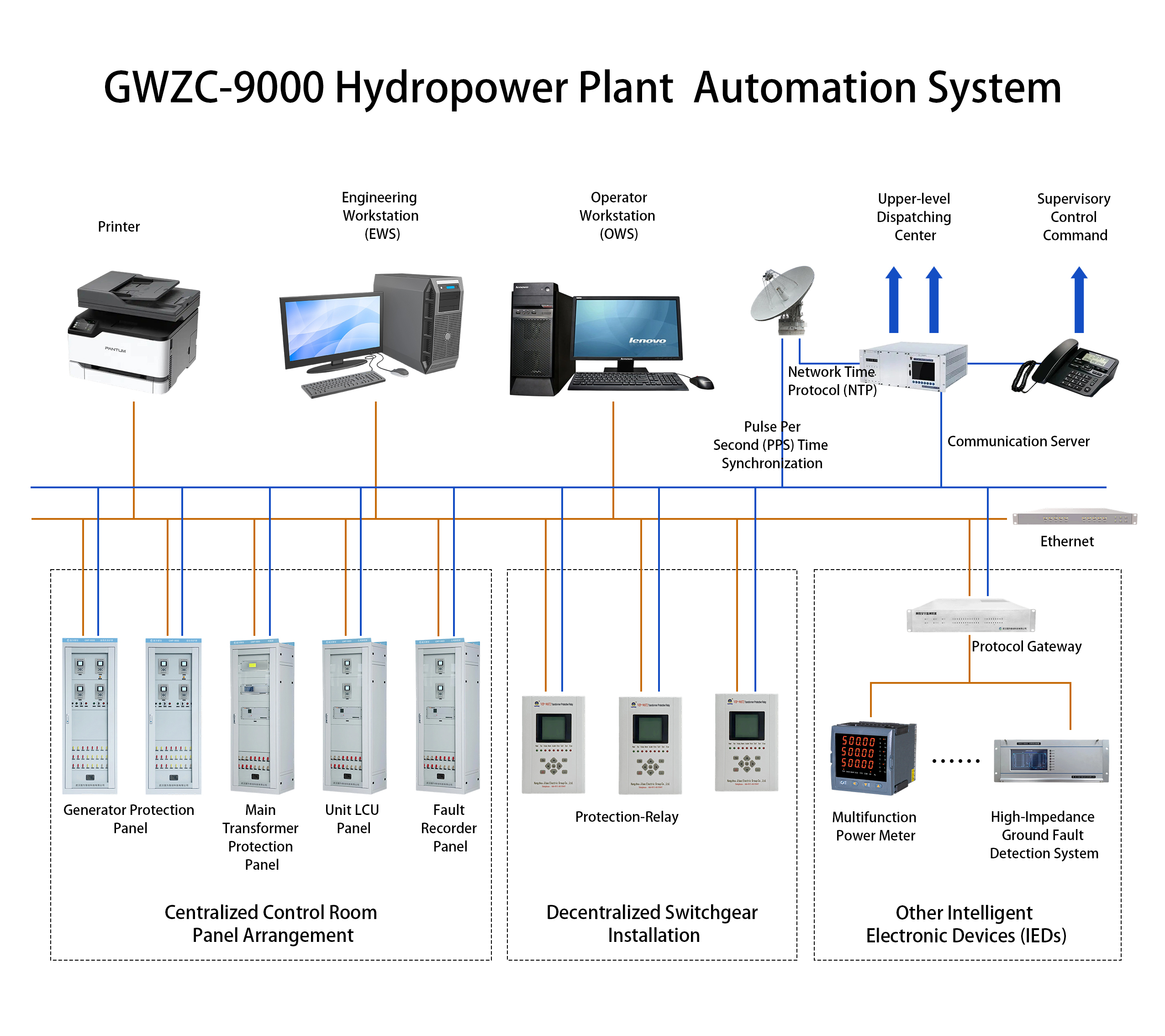
Key Characteristics:
Hierarchical and Distributed: Functions are decentralized, risks are spread, resulting in high reliability.
Networked: Based on high-speed Industrial Ethernet, facilitating easy information sharing.
Standardized: Adherence to international standards like IEC 61850 ensures device interoperability and system openness.
Intelligent: Extensive use of IEDs with powerful computing, communication, and self-diagnostic capabilities.