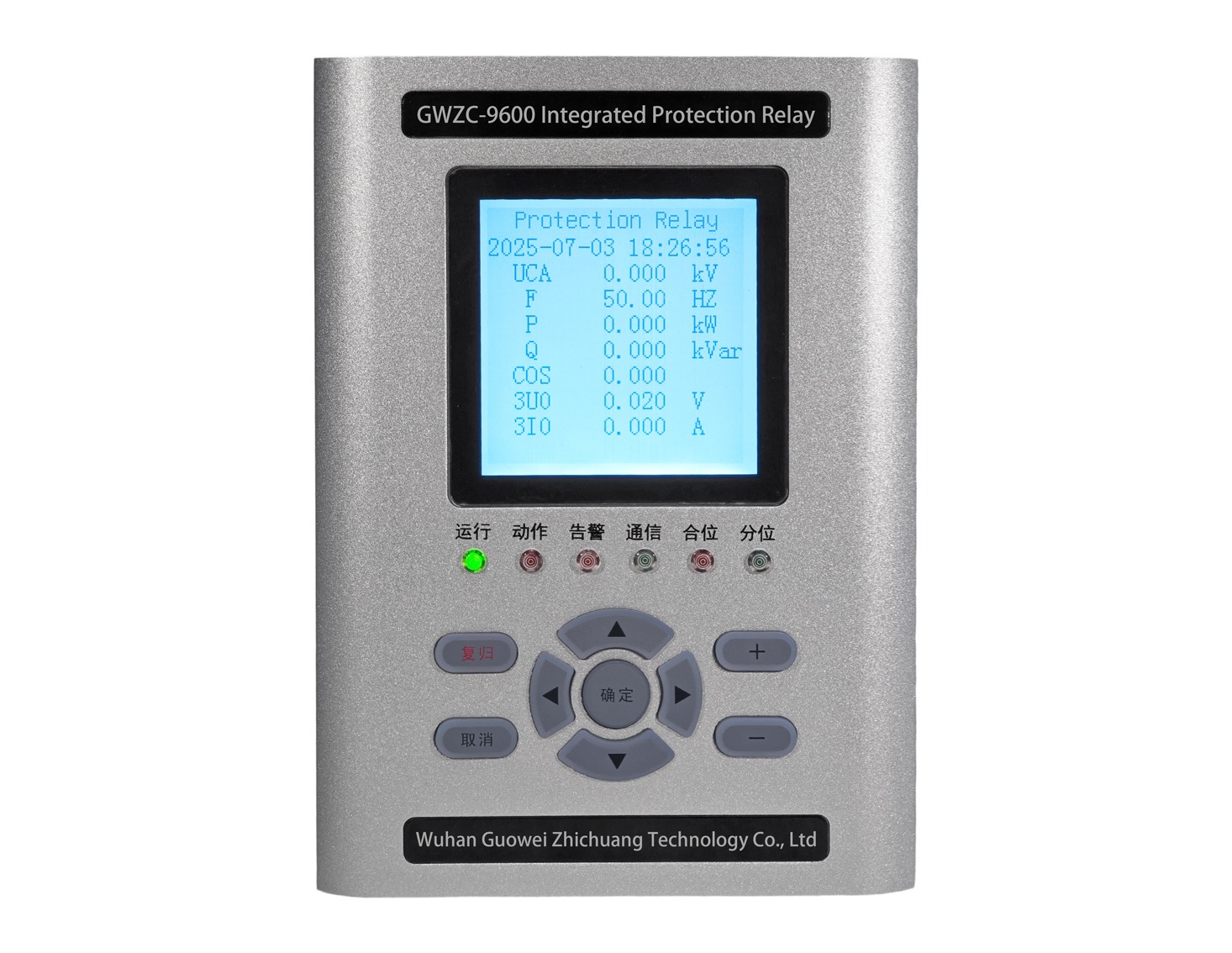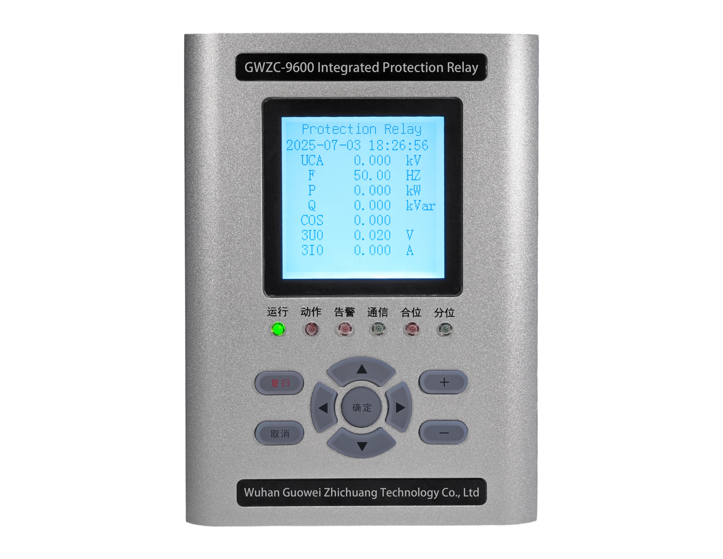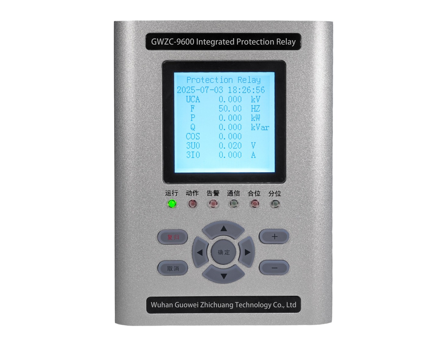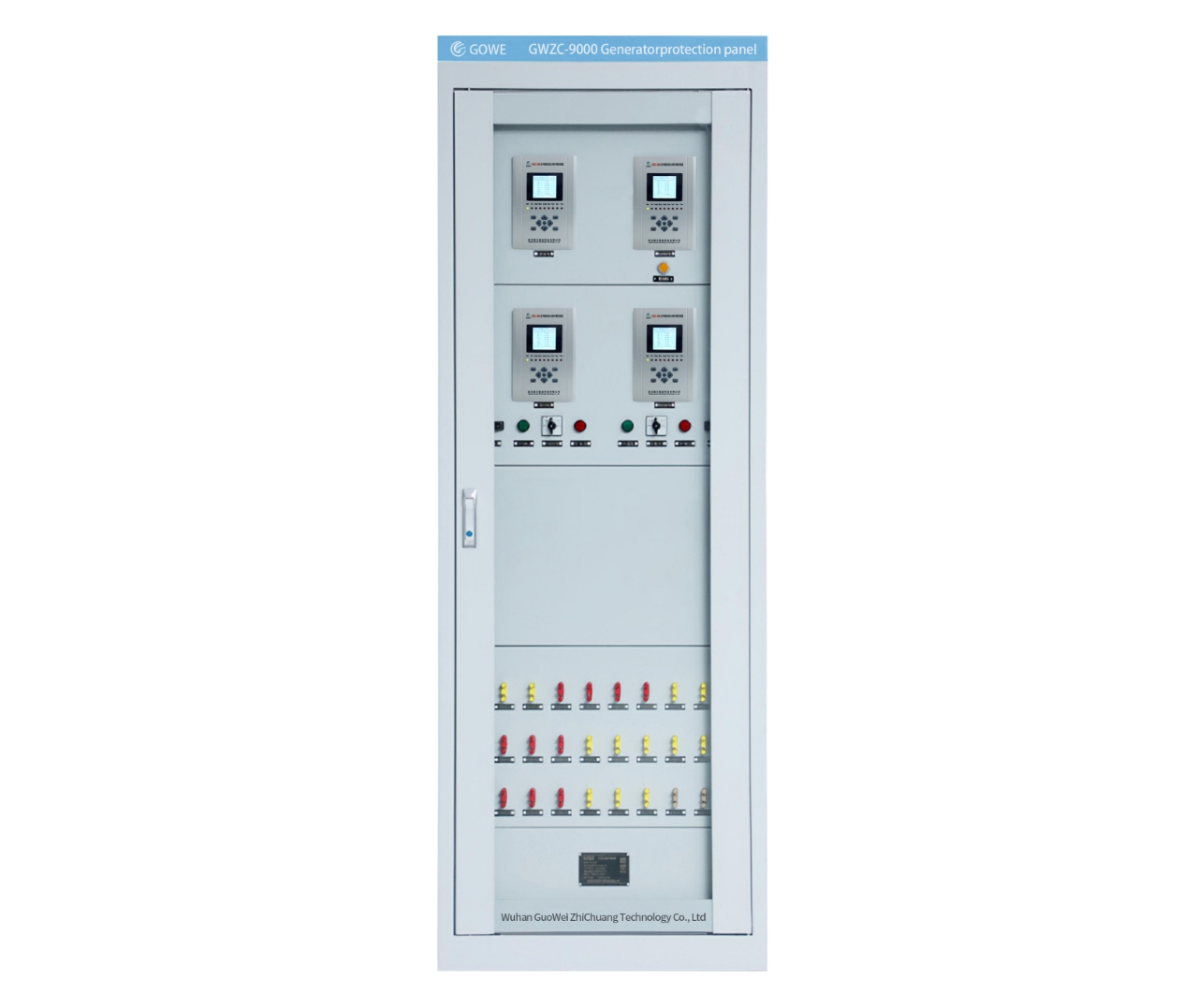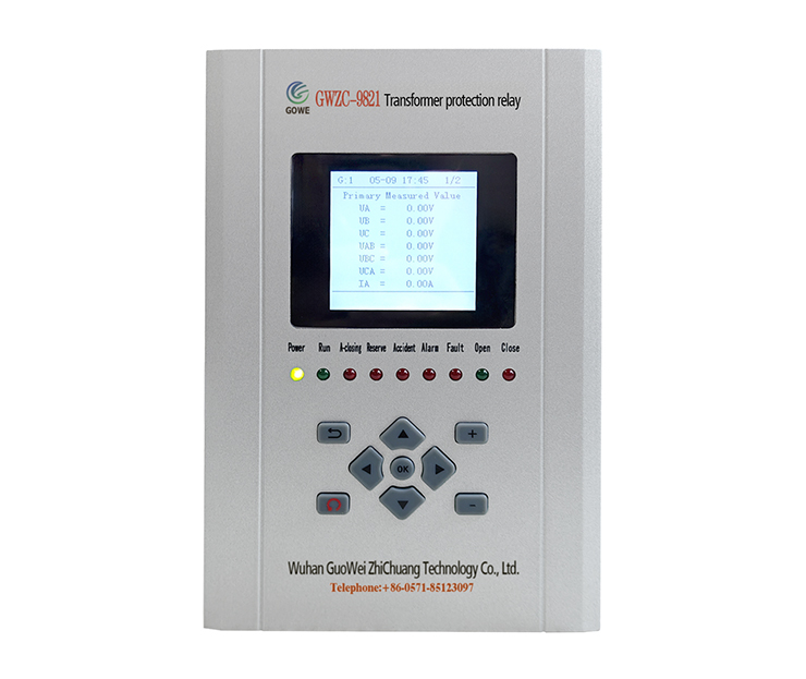
Directional overcurrent protection is primarily used for transmission line protection relay, while bus protection relay requires fast and reliable fault clearance. Although their protection objectives differ, directional overcurrent protection can be configured with additional logic to indirectly provide bus protection. Below is the detailed implementation method.
1. Basic Principles
Directional Overcurrent Protection: Detects current direction and magnitude to determine fault location (internal or external to the line).
Bus Protection: Must quickly identify bus faults and coordinate with adjacent line protection to avoid over-tripping.
2. Implementation Methods for Bus Protection Using Directional Overcurrent Protection
Method 1: Directional Overcurrent Protection + Logic Blocking (Simple Bus Protection)
Install directional overcurrent protection on all incoming/outgoing circuit breakers connected to the bus, with the direction set toward the line (reverse direction for the bus side).
Set a short time delay (e.g., 0.3–0.5s) for bus fault discrimination.
2.Operation Logic
During Bus Fault:
All directional overcurrent relays detect reverse fault current (flowing toward the bus) exceeding the threshold.
If multiple lines simultaneously detect reverse fault current, a bus fault is confirmed, tripping all connected breakers.
During Line Fault:
Only the faulted line’s directional overcurrent relay operates (forward direction), while others remain stable.
3.Pros & Cons
Advantages: No dedicated bus protection required, cost-effective.
Disadvantages: Relies on multi-line coordination, slower operation (requires delay to prevent misoperation); suitable for low-voltage distribution systems.
Method 2: Directional Overcurrent Protection + Current Differential (Enhanced Reliability)
Install CTs on all bus-connected lines to measure current.
Use directional overcurrent protection for fault direction discrimination, combined with current differential logic (ΣIin ≈ ΣIout).
2.Operation Logic
Differential Activation: When the current imbalance exceeds the threshold (indicating a bus fault), protection is triggered.
Directional Blocking: If a line’s directional overcurrent relay detects forward current (toward the line), bus protection is blocked to prevent misoperation.
No Blocking Signal: Differential protection directly trips the bus breakers.
3.Pros & Cons
Advantages: High reliability, suitable for critical busbars.
Disadvantages: Requires differential protection equipment, higher cost.
3. Key Considerations
Direction Discrimination
Ensure correct CT polarity to avoid misjudgment (reverse for bus faults, forward for line faults).
Setting Coordination
The directional overcurrent delay must exceed the line protection time to prevent over-tripping (e.g., line protection at 0.2s, bus protection at 0.5s).
CT Saturation Issues
For close-in bus faults, CT saturation may cause incorrect direction detection; use anti-saturation algorithms or high-accuracy CTs.
Communication Requirements
If multi-line coordination is needed, fast signaling (e.g., GOOSE or hardwired connections) must be implemented.
4. Typical Applications
35kV and Below Distribution Busbars: Method 1 (directional overcurrent + logic blocking).
110kV and Above Critical Busbars: Recommended to use Method 2 (directional overcurrent + differential) or dedicated bus protection.
5. Conclusion
By leveraging directional overcurrent protection with multi-line coordination or differential logic, a simplified bus protection scheme can be achieved. However, for high-voltage or complex bus systems, dedicated bus protection should be used to ensure selectivity and speed.
