Back to smartelemfg Home
Contact us Merchants settle in
Back to smartelemfg Home
Home -Technical

Bus Differential Protection: Functions, Features, and Working Principles​

Source: 2025-07-14 12:02:35

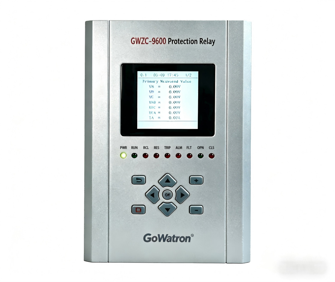
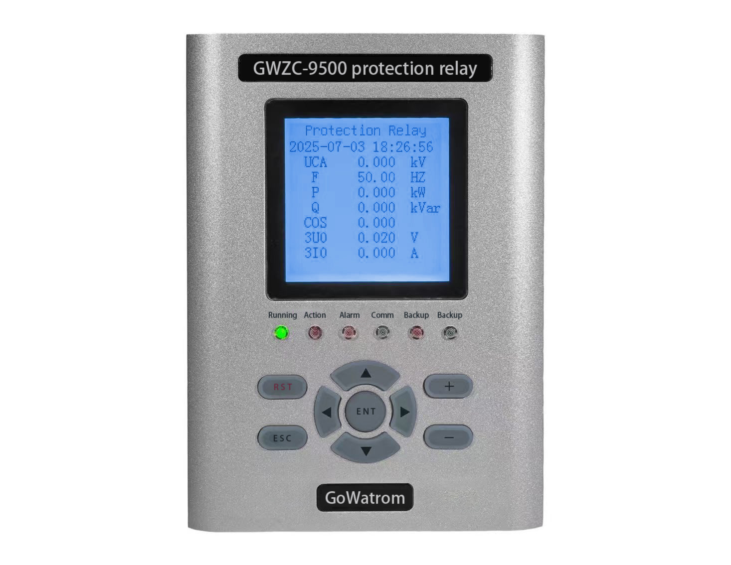
          Bus differential protection is a critical relay system in power systems, Bus differential protection relay designed to quickly isolate bus faults with high selectivity, speed, and reliability. 

​1. Role of Bus Differential Protection

​Instantaneous Fault Clearing​
          Detects and trips bus short-circuit faults (phase-to-phase or ground faults) within milliseconds to prevent system-wide damage.

​Selective Tripping​
          Only disconnects circuit breakers connected to the faulty bus, minimizing outage impact.

​System Stability Assurance​
          Prevents voltage collapse or cascading failures by isolating faults before they destabilize the grid.

​2. Core Functions of Bus Differential Protection

​Fast Operation for Internal Faults​
          Identifies bus faults by comparing the vector sum of branch currents (differential current).

​Restraint During External Faults​
          Remains stable for external faults (e.g., line faults) where differential current is negligible.

​CT Saturation Mitigation​
          Uses anti-saturation algorithms (harmonic restraint, time-delay compensation) to prevent false tripping.

​Adaptive Logic for Bus Reconfiguration​
          Automatically adjusts protection settings during bus switching operations.

​3. Working Principle of Bus Differential Protection 

​Current Balance Principle (KCL)​​
          ​Normal/External Fault Condition: I in =∑I out , differential current I d =0.​

          Internal Fault Condition: I d = ∑I in≠0, exceeding the preset threshold triggers tripping.

​Differential Protection Criteria​
          ​Operating Condition: I d >I set (differential current setting).
          ​Restraint Characteristic:I d >K⋅I restraint  to enhance security.

​4. Key Technologies & Classification

​Current Differential Protection​
          ​Full Differential: All CTs connected in parallel; requires matched CT characteristics.
          ​Partial Differential: Used for complex bus arrangements (e.g., with transfer buses).

​High-Impedance Differential Protection​
          Relies on voltage rise across a series impedance during faults; highly immune to CT saturation.

​Digital Differential Protection​
          Employs advanced algorithms (sampled-value differential, Fourier analysis) for faster, more reliable operation.

​5. Application Considerations

          ​CT Configuration: All branch CTs must have consistent ratios and polarities (software compensation if needed).
          ​Setting Coordination: Settings must account for maximum unbalanced current (CT errors, transient effects).
          ​Synchronized Sampling: Digital relays require precise time synchronization (e.g., GPS) for accurate current phasor comparison.

6. Coordination with Other Protection Systems

          ​With Line Protection: Bus protection acts faster than remote backup protection to ensure selectivity.
​         With Breaker Failure Protection: Serves as backup if a breaker fails to trip.

Product recommendations More
GWZC-9916 Bus differential protection relay
detail
GOWE-9000 Partial discharge online monitoring system
detail
GOWE-9000 Wireless Temperature Monitoring System for Substations
detail
GWZC-9604 Feeder Arc Flash Protection Relay
detail
GWZC-9804 Arc Flash Protection Relay
detail
Technical More
Wireless Temperature Monitoring System for Substations
Wireless Temperature Monitoring System: Application in Switchgear​
This article introduces the application of wireless temperature monitoring systems in high-voltage and low-voltage switchgear. The configuration of the wireless temperature monitoring system varies across different equipment. If you need a customized wireless temperature monitoring solution for your project, please visit our website for more information.
2025/09/08
GWZC-9804 Arc Flash Protection Relay
Switchgear Arc Flash Protection System Configuration Scheme
This article introduces the configuration scheme for a switchgear arc flash protection system. Busbar arc flash protection monitors the busbar compartment and trips the incoming breaker, while feeder arc flash protection monitors the circuit breaker compartment and cable compartment to trip the feeder breaker. A proper arc flash protection system configuration scheme can effectively protect personnel and equipment safety. For information on a reliable arc flash protection system configuration scheme, please visit our website.
2025/09/04
Arc Flash Protection Relay
Arc Protection Working Principle and Decision Process
Arc Flash Protection is a specialized safety system engineered to rapidly detect and mitigate destructive electrical arc flash faults. Unlike conventional overcurrent protection, it utilizes a combination of light and current sensors to identify an arc flash event within milliseconds. By triggering a circuit breaker to isolate the fault incredibly fast, Arc Flash Protection significantly reduces the explosive energy released, safeguarding personnel from severe injury and preventing extensive damage to electrical equipment like switchgear. This makes it an indispensable defense layer in industrial, commercial, and utility power systems.
2025/09/03
Motor Protection RelayRear View
Accelerated Protection Role, Function, and Principle
Accelerated protection mechanisms in protection relays ensure quick response to faults, minimizing damage and enhancing system stability by understanding its role, function, and principle.
2025/09/02
Inquiry Consultation
+86-17621210051
+86-17621210051
+86-17621210051
+86-17621210051
home product email
live chat
my