Back to smartelemfg Home
Contact us Merchants settle in
Back to smartelemfg Home
Home -Other Relays
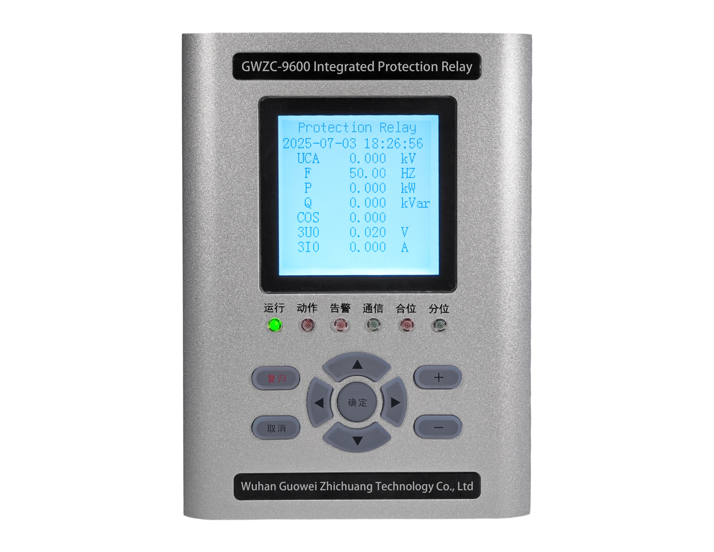
GWZC-980​3 Automatic Synchronizing Device (ASD)​
GWZC-980​3 Automatic Synchronizing Device (ASD)​ Side View
GWZC-980​3 Automatic Synchronizing Device (ASD)​ Rear View
GWZC-980​3 Automatic Synchronizing Device (ASD)​
GWZC-980​3 Automatic Synchronizing Device (ASD)​ Side View
GWZC-980​3 Automatic Synchronizing Device (ASD)​ Rear View
GWZC-980​3 Automatic Synchronizing Device (ASD)​

Applicable Scope :Applicable Scope: Designed for 11kV & 33kV power systems (default per model code ’98’). Supports generator-grid synchronization with voltage range 60-120% Un, frequency range ±10% Fn, and phase angle tolerance ±5°. Operating temperature -25°C to +70°C.

Product functions(ANSI):25 | 25/79 | 27/79 | 39/50BF

Communication functions :Supported Protocols :​​ IEC 60870-5-103 (over Ethernet) | MODBUS RTU (via RS-485) | IEC 61850 (Ed.2 or Ed.1, as applicable)
​Interfaces:​​2× Ethernet Ports​ (IEEE 802.3 compliant, 10/100 Mbps) | 2× RS-485 Ports​ (ANSI/TIA-485-A standard, galvanically isolated)

Product Introduction Technical Parameter Size

GWZC-9803 Automatic Synchronizing Device (ASD) Introduction

          GWZC-9803 Automatic Synchronizing Device (ASD) ensures seamless generator-grid connection for high-voltage substations (33kV/66kV). Key features include microprocessor-based phase angle calculation, automatic voltage/frequency regulation assistance, and anti-reverse power protection. Equipped with dual communication interfaces and event recording for grid operation analysis.

GWZC-9803 Automatic Synchronizing Device (ASD) Functions and Characteristics​

Primary Functions (ANSI Codes):​​

  1. Automatic Synchronizing (Frequency and Voltage Control) (ANSI 25)
  2. Loop Closing (ANSI 25/79)
  3. Dead Line Closing (ANSI 27/79)
  4. Circuit Breaker Timing Test (ANSI 39/50BF)


Communication Functions:​​

  1. Protocols: IEC 61850 (Optional), Modbus, DNP3.0, Ethernet RS485.
  2. Interfaces: 2×RJ45 ports for high-speed data exchange (100Mbps), enabling seamless SCADA integration.

​Key Characteristics:​​

  1. ​Processing and Memory: 32-bit DSP core with 512KB FRAM (ensures 10-year data retention for fault logs).
  2. ​Measurement Accuracy: Monitors |Z|, Φ, I0, V0 with 0.2% precision for reliable fault discrimination.
  3. ​Input/Output Flexibility: 7×CT/VT inputs and 10×programmable relays for customizable trip circuits.
  4. ​Logic Configuration: LOGIC>EDIT™ graphical editor for easy protection logic programming.
  5. ​Trip Circuit: 250V AC/DC rated with seal-in monitoring to prevent nuisance operati ns.
  6. ​Time Synchronization: IRIG-B/PPS support (±1μs accuracy) for coordinated event recording.
  7. ​Anti-Maloperation: Adaptive TV algorithm filters noise to avoid false triggering.
  8. ​Communication: Dual Ethernet and fiber interfaces for redundant connectivity.
  9. ​Data Recording: 32-cycle COMTRADE waveform capture for detailed fault analysis.
  10. ​Low Power Design: <5W operation (compatible with 24-220V DC/AC supplies).
  11. ​EMC Robustness: Class IV certification (IEC 60255-26) for electromagnetic compatibility.
  12. ​Environmental Tolerance: Operates from -40°C to +85°C, ensuring reliability in extreme conditions.

GWZC-9803 Automatic Synchronizing Device (ASD) Working Principle​

          The GWZC-9803 ASD automatically synchronizes a generator or power source with a running bus (grid) to enable safe, smooth connection by ensuring key parameters meet predefined thresholds before closing the circuit breaker.

​Core Synchronization Conditions​

The device verifies three critical factors:

  1. ​Voltage Match: The generator voltage (Ug) and bus voltage (Ub) must differ by ≤±5% (adjustable).
  2. ​Frequency Match: The frequency difference (Δf = fg – fb, where fg is generator frequency, fb is bus frequency) must be minimal (typically 0.1–0.5 Hz) to avoid mechanical stress.
  3. ​Phase Angle Match: The phase difference (Δθ) between Ug and Ub must be within ±10° (adjustable) to prevent surges.
  4. Additionally, it checks that the generator and bus share the same phase sequence (e.g., ABC) to avoid short circuits.

Working Process​

  1. ​Real-Time Monitoring: The ASD continuously measures Ug, Ub, fg, fb, and phase angles.
  2. ​Parameter Adjustment (if needed)​: If conditions are unmet, it sends signals to the generator’s governor (to adjust speed/frequency) and AVR (to adjust voltage) until values fall within limits.
  3. ​Optimal Timing Calculation: It predicts the ideal breaker-closing moment—typically when Δθ ≈ 0° (or a slight lead/lag) to minimize transient impacts.
  4. ​Breaker Closure: Once all parameters (ΔU, Δf, Δθ) are within safe ranges, the ASD triggers the circuit breaker at the optimal instant.
  5. ​Protection: If abnormal conditions (e.g., excessive slip, voltage spikes) arise, it aborts synchronization to prevent damage.

Operation Modes​

  1. ​Manual: Operators initiate sync based on ASD-displayed data.
  2. Automatic: The device fully automates the process without manual input.

Electrical Specifications​

​Power Supply:​​

● AC: 85-264V, 47-63Hz (≤15% THD)
● DC: 100-370V (≤5% ripple)

​Rated AC Parameters:​​

● Voltage: 100V/√3 or 100V
● Current: 5A/1A
● Frequency: 50Hz

​Overload Capacity:​​

● Current Circuit: 2×In continuous | 10×In (10s) | 40×In (1s)
● Voltage Circuit: 1.5×Un continuous

​Power Consumption:​​

● Supply: <10W (static), ≤15W (trip)
● Current Circuit: ≤1VA/phase (5A) / ≤0.5VA/phase (1A)
● Voltage Circuit: ≤0.5VA/phase

​Digital Output:​​

● Dry contact (8A@250VAC / 30VDC)
● Dielectric: 4kVAC (coil-contact), 1kVAC (open contact)
● Operating Time: 5ms (typ) / 8ms (max)
● Mechanical Life: 100k operations

​Protection Performance​

​Operating Range:​​

● Voltage: 0.5-120V (phase)
● Current: 0.02-20×In
● Zero-Seq Current: 0.05-20A
● Frequency: 35-65Hz | Delay: 0-100s

​Accuracy:​​

● Voltage/Current: ±2.5% or ±0.1V/±0.05A (whichever greater)
● Frequency: ±0.01Hz
● Settings: ±2.5%

​Trip Time:​​

● Instantaneous: ≤35ms (≥1.2× setting)
● Time-Delayed: ≤1% of setting or 35ms

Measurement & Monitoring​

​Range:​​

● Voltage: 0.5-120V | Current: 0.02-1.2×In

​Accuracy:​​

● V/I: ±0.2% | Frequency: ±0.01Hz | Other: 0.5%
● Time Sync: ≤2ms | SOE: ≤1ms

​Event Recording:​​

● 128 protection trips/operations
● 32 self-tests/fault waveforms (COMTRADE)

​Environmental & Mechanical​

​Operating Temp:​​

● Standard: -10°C to +55°C
● Extended: -40°C to +70°C*

​Storage Temp:​​ -40°C to +80°C
​Humidity:​​ 5-90% RH (non-condensing)
​Pressure:​​ 60-110 kPa
​Compliance:​​

● IEC 60255-21 (vibration/shock)
● IEC 61000-6 (EMC)
Related products More
GWZC-9802 Directional Earth Fault Relay (DEF Relay)
GWZC-9802 Directional Earth Fault Relay
detail
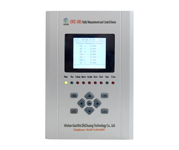
GWZC-9801 Public Measurement and Control Device
detail
GWZC-9872 Loop closing protection relay
detail
GWZC-9000 Sewage Treatment Automation Control System
detail
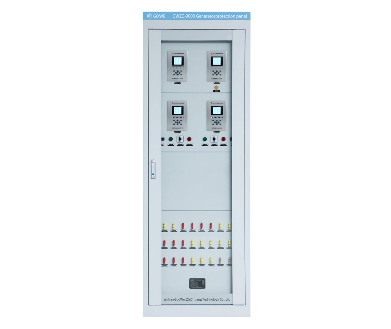
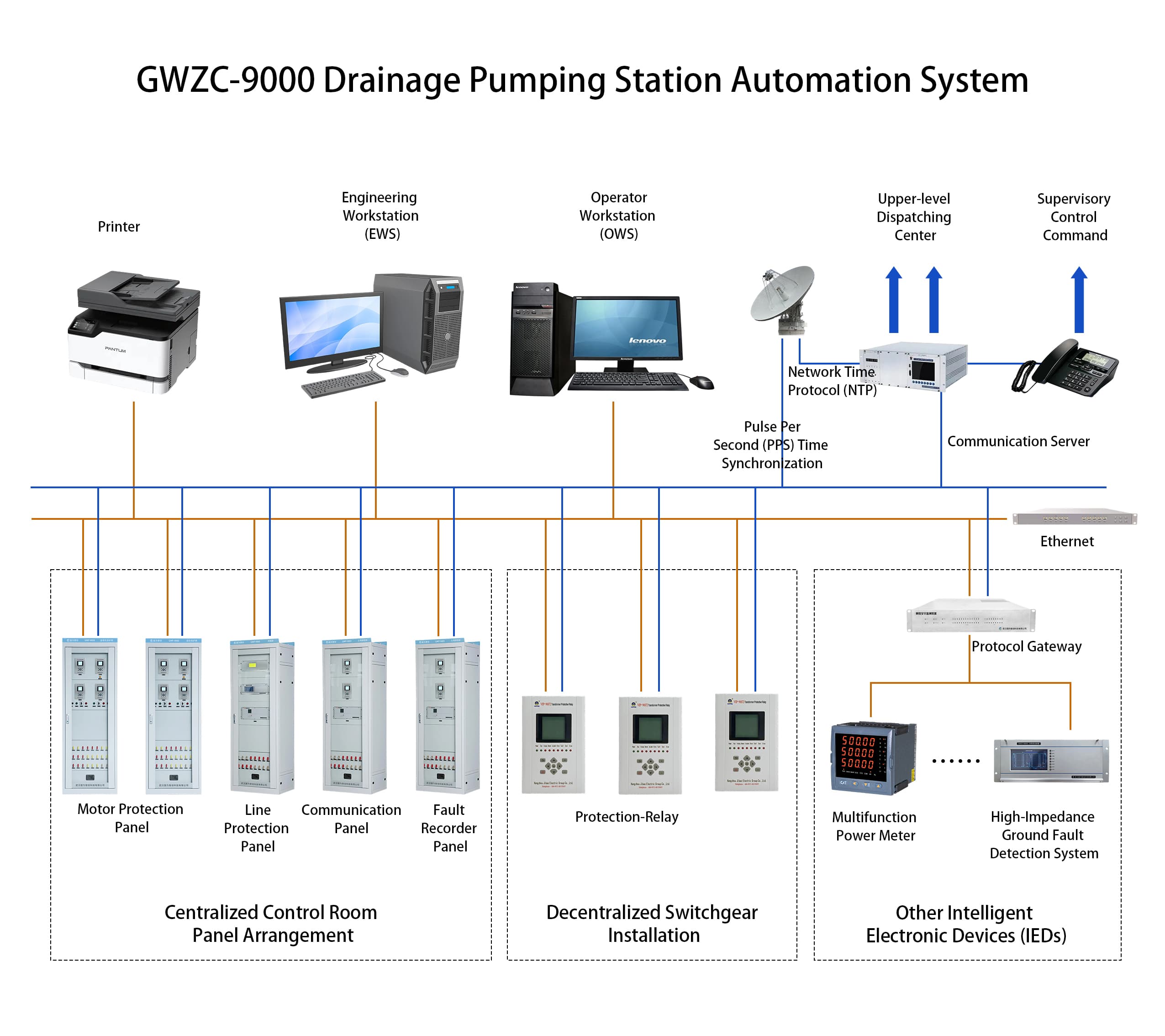
GWZC-9000 Drainage Pumping Station Automation System
detail
Technical Knowledge More
overcurrent protection and Overload Protection
Difference Between Overcurrent Protection and Overload Protection
Overcurrent protection and overload protection are critical mechanisms in electrical systems, yet they serve distinct purposes. Overcurrent protection focuses on safeguarding against sudden, high-magnitude currents (e.g., short circuits), while overload protection addresses prolonged, slightly elevated currents (e.g., excessive loads). This guide details their core objectives, trigger conditions, action timelines, applications, and typical devices, helping clarify their roles in maintaining electrical safety.
2025/08/26
Automatic Transfer Switch (ATS) Side View
What is Parallel Operation
​Parallel operation​ involves connecting two or more independent AC power sources (e.g., generators, grids) to share electrical loads seamlessly. This process—synchronization—demands precise matching of voltage magnitude, frequency, and phase angles between systems before interconnection. Critical for grid expansion, backup power, and renewable integration, it enables redundant supply during failures.
2025/08/15
Generator-Transformer Differential Protection Relay Rear View
Ring-Closing Operation: Definition & Importance in Power Grids
A ring-closing operation involves closing a normally open switch within a closed-loop electrical network fed by a single power source. This creates parallel paths to redistribute loads without interruption, primarily for maintenance or network reconfiguration. Key prerequisites are voltage difference under 5%, phase angle alignment below 5 degrees, and pre-calculation of induced circulating currents to avoid equipment damage. Distinct from connecting independent systems, this procedure requires advanced monitoring but avoids synchronization complexity. Strict protocols using real-time sensors and simulations ensure safe execution, making it fundamental for resilient distribution networks like ring-main units (RMUs) in urban grids.
2025/08/14
GWZC-980​3 Automatic Synchronizing Device (ASD)​
GWZC-980​3 Automatic Synchronizing Device (ASD)​ Side View
GWZC-980​3 Automatic Synchronizing Device (ASD)​ Rear View
Inquiry Consultation
产品表单
Inquiry Consultation
+86-17621210051
+86-17621210051
+86-17621210051
+86-17621210051
home product email
live chat
my