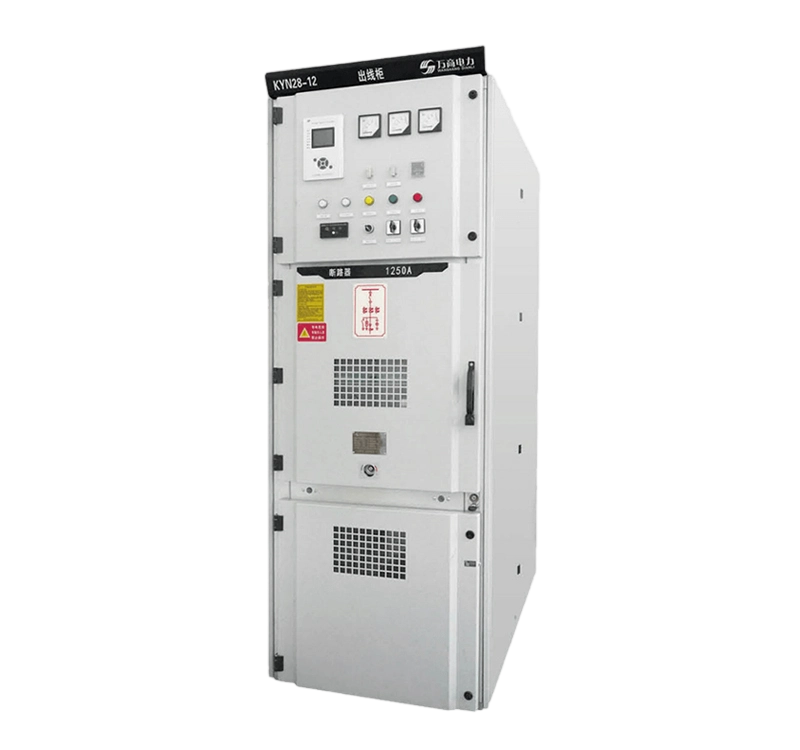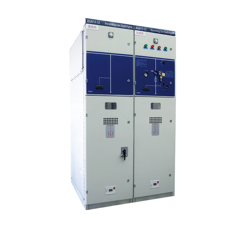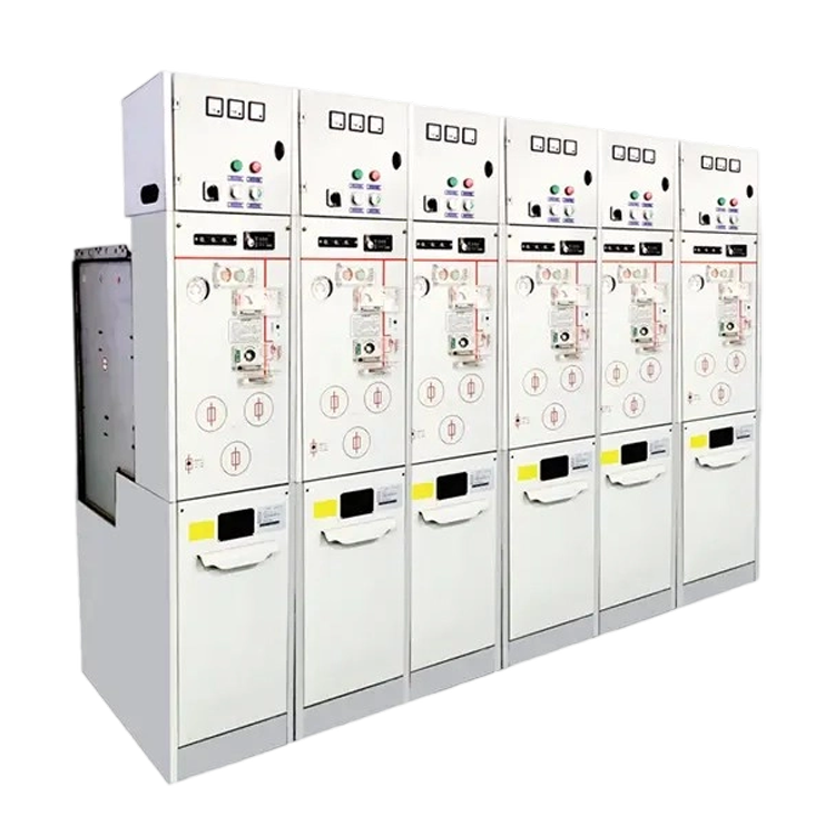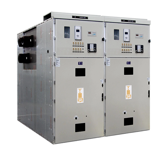


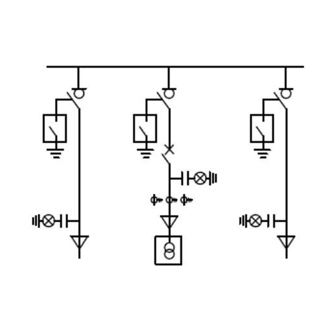
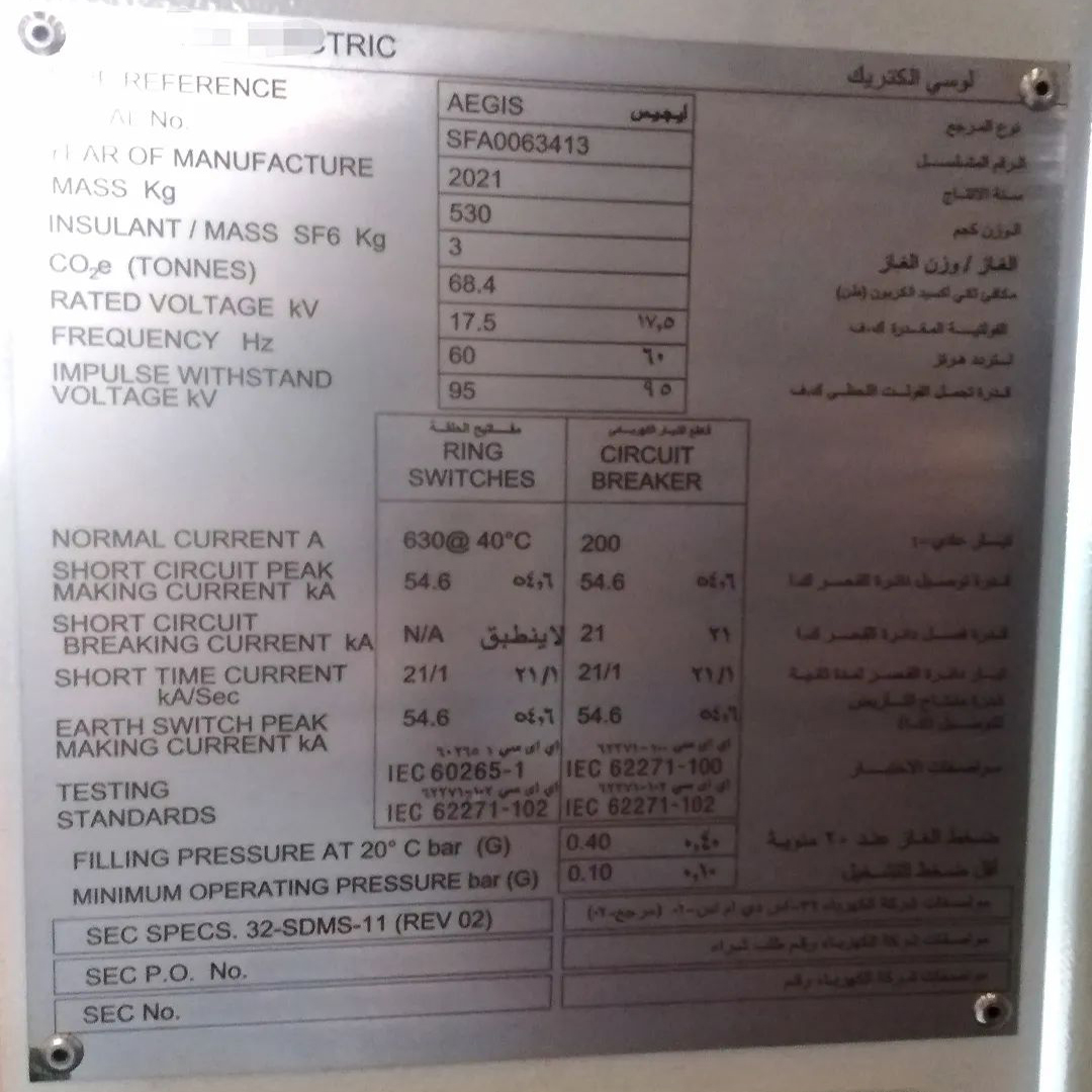
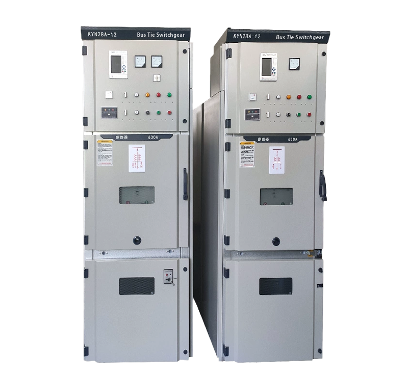
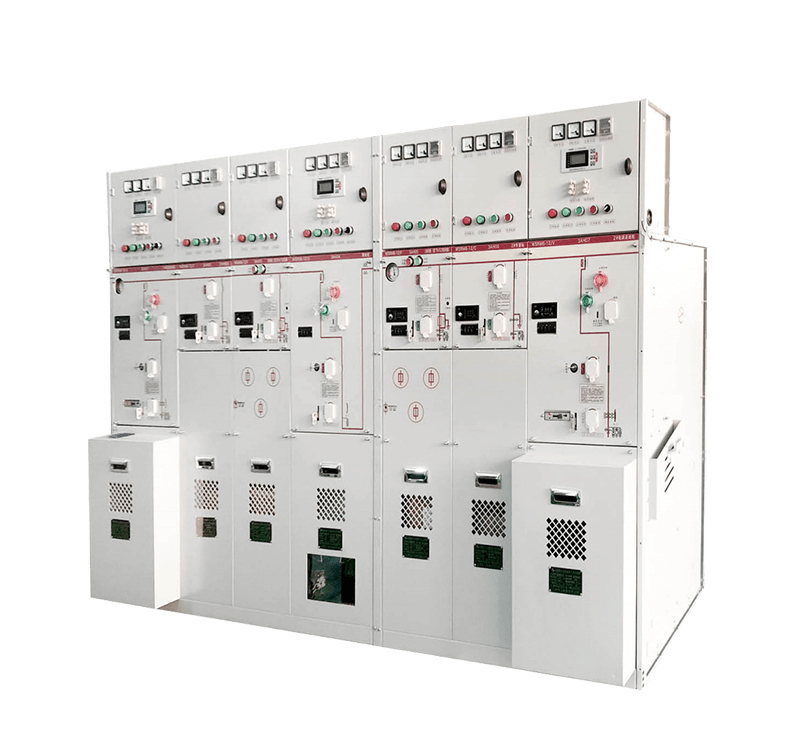
SEC Specifications: 17.5kV Ring Main Unit (RMU) – Key Features
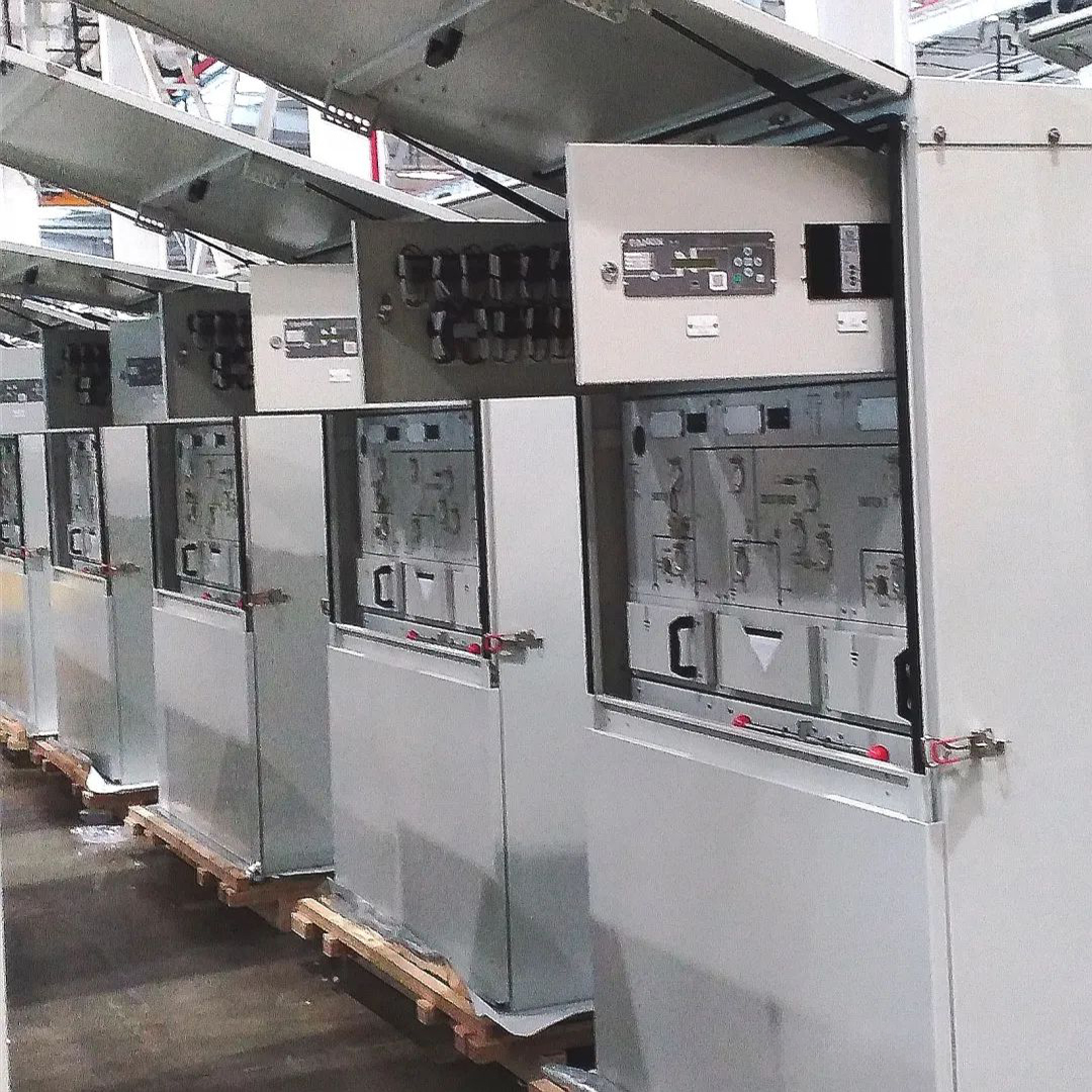
Outdoor Enclosure: Designed for outdoor installation.
Dedicated Cable Withstand Voltage Test Terminal Compartment: Features a separate, accessible compartment for cable high-potential (Hi-Pot) testing.
Self-Powered Protection Unit: Utilizes an internal power source for the protection relay.
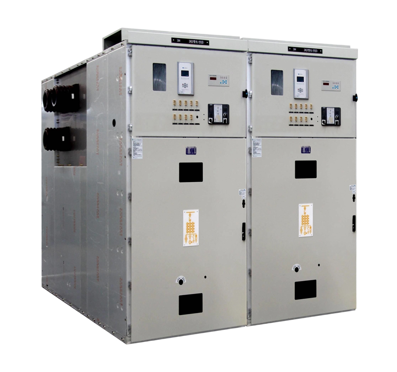
SF6 Insulated, Single-Tank Design F+F+V Configuration: Common SF6 gas tank housing a combination of Load Switch (F) + Load Switch (F) + Circuit Breaker (V).
Ratings: Ring Switch Unit: 630A. Feeder Circuit Breaker: 200A.
Compliance Standard: SEC Standard 32-SDMS-11.
SEC Standard RMU Parameters:
Rated System Voltage: 13.8kV
Equipment Rated Voltage: 17.5kV
Rated Frequency: 60Hz
Rated Short-Time Withstand Current (I_sc): 21kA for 1 second
Rated Peak Withstand Current (I_p): Calculated as I_sc * 2.6 (for 60Hz) = 21kA * 2.6 = 54.6kA
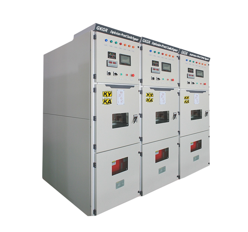
Design and Construction:
SF6 Insulated, Common Tank: Provides insulation within a single pressurized SF6 enclosure.
IP54 Protection Rating: Ensures dust and water ingress protection suitable for direct outdoor application.
Flip-Up Cover Design: Upper section features a hinged flip-up cover for convenient access to secondary control, protection equipment, and status viewing.
Compact Height Profile: Prioritizes reduced overall height for outdoor cabinet installation accommodating an instrumentation compartment. To achieve this:
Conventional vertical stacking (three-position switch + circuit breaker) is avoided due to excessive height.
A horizontal side-by-side arrangement of the Three-Position Switch (TPS) and Vacuum Circuit Breaker (VCB) interrupter units is employed.
Width Consideration: Width requirements are less stringent compared to typical domestic designs (e.g., 350mm+350mm+350mm = 1050mm). An overall width within 1500mm is acceptable. LUCI switchgear dimensions serve as a design reference.
Cable Withstand Voltage (Hi-Pot) Test Terminal:
For the compact SF6 load switch units, the grounding contact of the Three-Position Switch (TPS) is connected via a solid copper bar to a dedicated test bushing located on the front of the switchgear tank.
Testing Procedure:
Load switch is in the CLOSED position.
High-voltage test equipment is connected to the test terminal.
Voltage is applied directly to test the cable insulation.
Post-Testing Procedure:
Disconnect test equipment.
Reconnect the grounding shorting link to the test terminal.
Close the test compartment door.
The grounding switch can now be operated (OPENED) to resume normal TPS functionality.
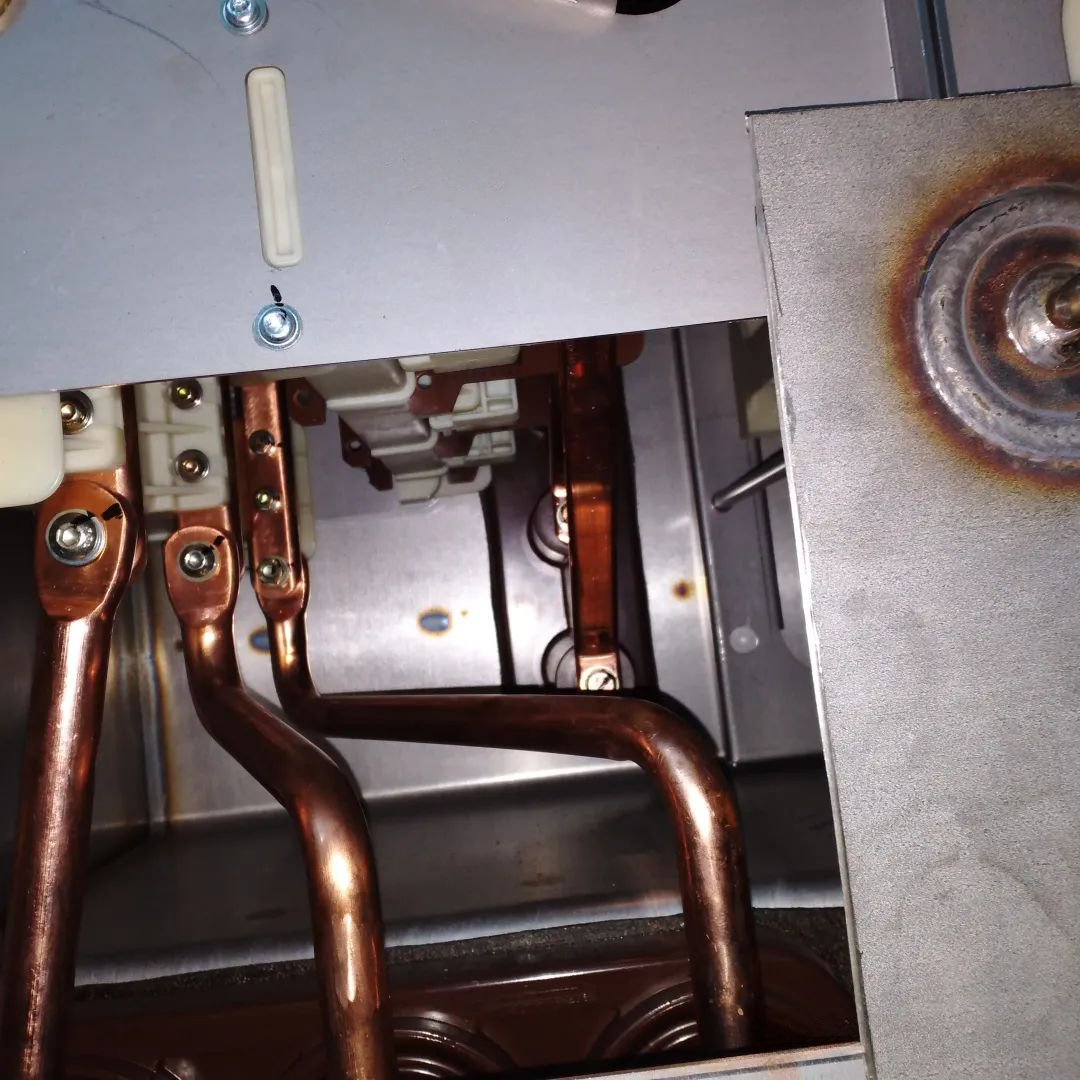
Copper Bar Requirement: The copper bar connecting the TPS grounding contact to the test bushing must withstand the rated short-circuit current. Its cross-sectional area must be sufficient to ensure:
Compliance with the grounding switch’s making capacity.
Adequate dynamic and thermal stability (I_sc 21kA for 1s) to prevent failure under fault conditions.
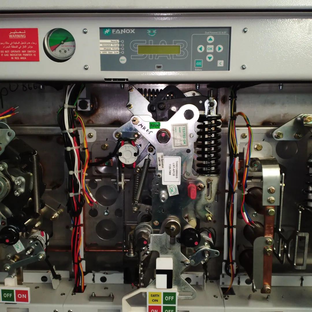
Self-Powered Protection System:
Employs a passive protection relay (e.g., WIC1 type).
Utilizes a low-energy trip coil for circuit breaker operation.
Operation Principle: Upon loss of external auxiliary power, if a fault current exceeding the trip threshold is detected, the passive protection relay generates an electromagnetic signal. This signal directly actuates the low-energy trip coil, mechanically tripping the circuit breaker’s operating mechanism.
Furthermore, the enclosure protection is achieved not via a separate ring main unit (RMU) plus outdoor cabinet, but through a monobloc design. In this integrated design, the cable compartment forms an integral part of the outer enclosure, meeting sealing and waterproofing requirements. The upper section features a flip-up cover which, when opened, provides easy access for viewing switch status, inspecting protection relays, checking secondary circuits, and performing maintenance.
An integrated voltage transformer (VT) for the power supply is employed. The VT directly charges the battery, which then supplies power to the secondary control circuits and the circuit breaker operating mechanism via a power supply module, eliminating the need for an external power source. Secondary control and status circuits utilize communication protocols, enabling management communication with the remote SCADA/back-end system via a single-core cable link.


.png)