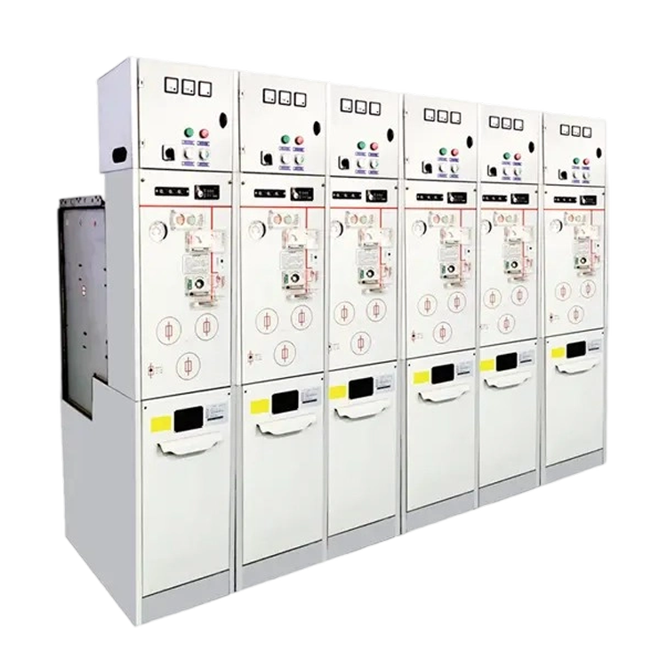


The design of Medium Voltage switchgear must account for numerous factors, with insulation being paramount. An insulation scheme must be established, determining the method of insulation—whether air insulation, gas insulation, solid insulation, or air compound insulation, among others. For pure air insulation, the applicable standards for air insulation clearance distances must be met.

This point is very clear. For slightly non-uniform electric fields, the lightning impulse withstand voltage dictates the air clearance between live conductors or to earth. Both IEC and GB/DL standards provide explicit definitions. Failure to meet this minimum air clearance will likely result in the inability to pass the lightning impulse withstand voltage test. Conversely, meeting this requirement ensures a greater than 99% probability of passing the lightning impulse test. Exceeding this standard’s minimum required distance allows the client to accept that the corresponding lightning impulse withstand voltage is satisfied, meaning testing is unnecessary. For example, for an IEC voltage level of 17.5kV with a lightning impulse withstand voltage of 95 kV, using air insulation requires a clearance ≥ 160 mm. Domestic GB standards for 12kV Medium Voltage switchgear require ≥ 125 mm, which is insufficient to pass the 95 kV lightning impulse withstand voltage test, thus making it unsuitable for 17.5kV applications.
Table 1 of Appendix A to IEC 60071: Relationship between the rated lightning impulse withstand voltage and the minimum air distance (at an altitude of 1000 m)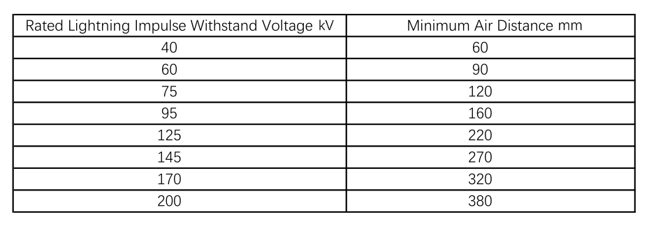
Similarly, employing other insulation methods requires adherence to their respective design standards. During design, the distances at all critical points must be measured and must exceed the requirements stipulated by the standards.
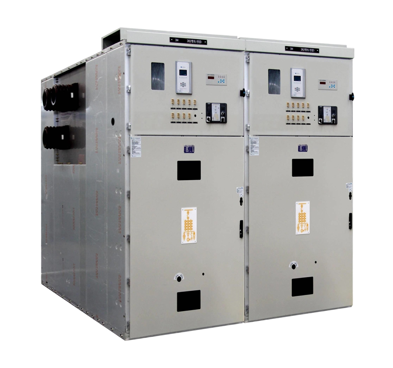
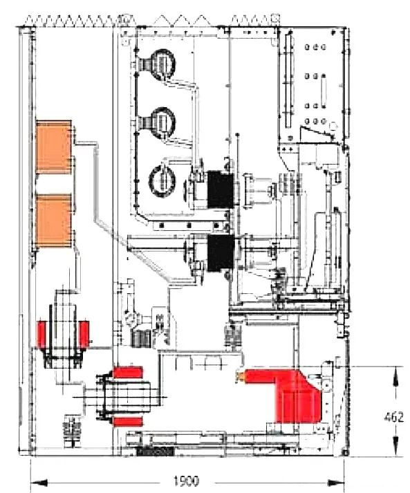
Based on the sequence of components in the primary system layout, they should be arranged according to the required insulation distances: main busbar – upper branch busbar – contactor arm (or bushing) – circuit breaker – contactor arm (or bushing) – current transformer – earthing switch – outgoing cable connection busbar – voltage transformer.
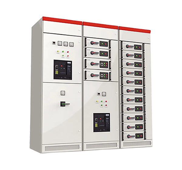
Consideration of Equipment Temperature Rise: Switchgear design must account for the temperature rise caused by additional heating from current flow. For components with high heat generation, such as the vacuum interrupter chamber and its upper/lower terminals of a vacuum circuit breaker, and the primary moving/fixed contacts of withdrawable circuit breakers, airflow must be considered to avoid heat concentration and inability to dissipate. Generally, instrument transformers can be placed farther from the contactor arm (bushing) to allow the busbar to help dissipate the high heat from the moving/fixed contact connections. Ventilation design is necessary at the bottom and top of the circuit breaker compartment.
Consideration of Busbar Dynamic and Thermal Stability: The spacing between busbar insulation supports must be calculated based on the equipment’s peak withstand current. The support for the main busbar also needs consideration. This is determined using the appropriate calculation formulas to establish the design principle. For instance, for 31.5 kA / 80 kA, with a phase spacing of 210 mm, the support spacing should not exceed 1 meter.
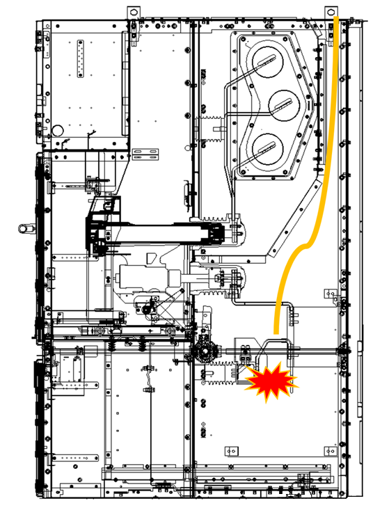
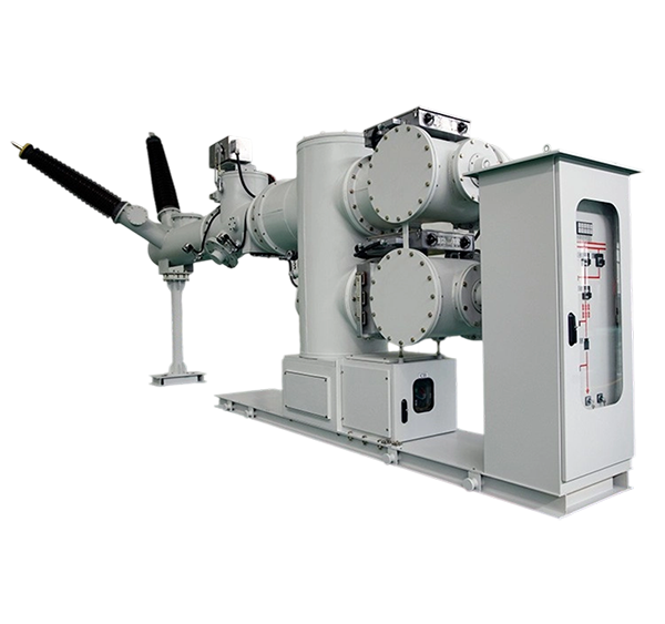
Consideration of Internal Arc Fault Pressure Release: The shockwave from an internal arc explosion needs to open the pressure relief flaps. This requires ensuring smooth pressure relief channels to reduce the opening time and enable rapid pressure release.
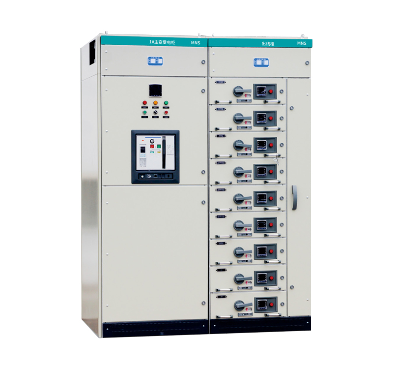
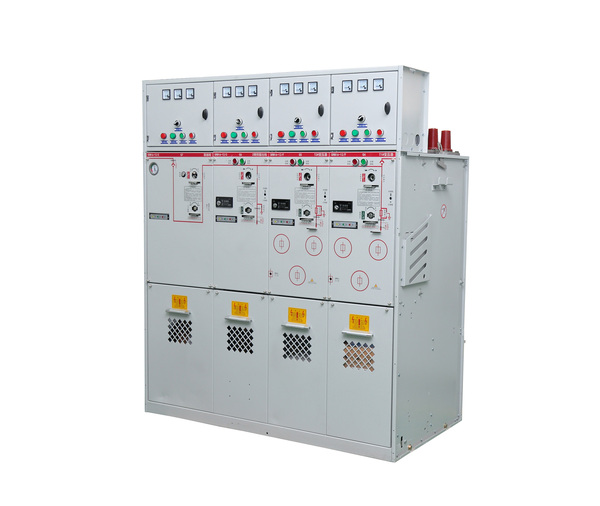
Ease of Installation and Maintenance: For non-standard projects, such as those where the client requires numerous windings necessitating multiple epoxy cast resin pillar-type current transformers, or sometimes through-type current transformers to meet PX class protection requirements, and also requires front-access operation and maintenance.
Deepening the cabinet body while placing the earthing switch at the very rear would require lengthening the operating shaft, increasing the operating torque and making it difficult to observe the status of the earthing switch from the front. Therefore, the earthing switch should remain in its original position within the standard switchgear configuration, eliminating the need for an extended operating shaft.
Multiple current transformers are installed at the rear of the panel to meet the requirements of the transformer windings. The voltage transformer truck is positioned at the front of the panel, allowing it to be connected to the cables and inserted into operation.


.png)