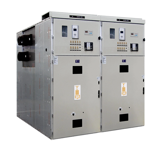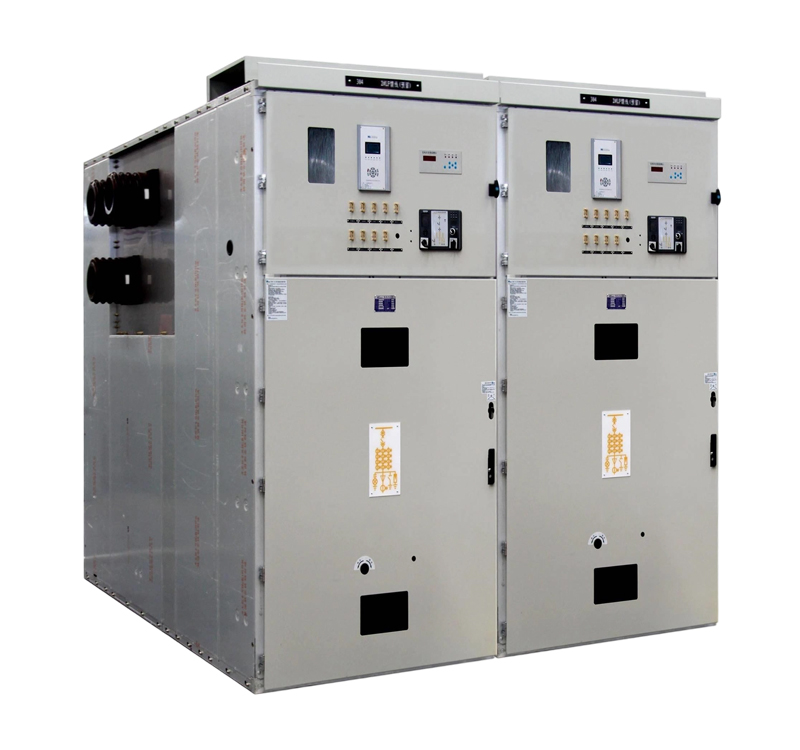


HVSC boxes are critical equipment providing high-voltage electrical power to berthed vessels. Their safe and reliable operation is paramount. Maintenance and management encompass safety, technical, operational, and documentation aspects. Key considerations are outlined below:
Ⅰ.Safety First – Core Principle
1.Strictly Adhere to “Lockout, Tagout, Tryout” (LOTO) Procedures:
Isolate: Before any maintenance, repair, or cleaning work, MUST isolate all power inputs (from shore substation) and outputs (to ship) to the High Voltage Shore Connection (HVSC) Box.
Tag: MUST attach prominent “DANGER – DO NOT OPERATE – PERSONNEL AT WORK” warning tags on isolating devices.
Lock: MUST secure isolating devices with safety locks, ensuring only authorized personnel can unlock them.
Restore: Upon completion, the person who applied the lock/tag (or authorized supervisor) MUST personally remove it.
2.Verify Complete Equipment Discharge:
Capacitors and other components may retain charge after isolation. MUST use dedicated, certified discharge rods to fully discharge high-voltage components (e.g., busbars, cable terminations, capacitors) according to procedures, and ensure reliable grounding.
Perform discharge and grounding wearing insulated gloves and using insulated tools.
3.Personal Protective Equipment (PPE):
Mandatory Requirement: Personnel entering high-voltage areas or performing operations/maintenance MUST wear compliant insulated gloves, dielectric footwear, safety glasses, hard hats. Arc-flash rated clothing may be required.
Use properly rated, calibrated insulated tools (e.g., screwdrivers, wrenches).
4.Work Permit and Supervision:
MUST implement a Permit-to-Work (PTW) system for internal HV work or complex repairs, specifying work scope, safety measures, responsible person, and safety observer.
MUST assign a qualified and experienced safety observer. The observer must focus solely on safety compliance and personnel status, not performing the work.
5.Emergency Procedures Familiarity:
All relevant personnel MUST be thoroughly trained in emergency procedures: electrical shock rescue (CPR), electrical fire suppression (use CO2 or dry powder extinguishers – NEVER use water), and evacuation routes.
Maintain certified first-aid kits and appropriate fire extinguishers on-site; inspect regularly.
II. Operation and Usage Standards
1.Certified Personnel Only:
Operators and maintainers MUST hold nationally recognized High Voltage Electrical Operation Certificates or equivalent permits, plus specific HVSC system training.
Conduct regular refresher training and safety briefings.
2.Strict Adherence to Operating Procedures:
Before each connect/disconnect operation, MUST verify compatibility between ship and shore systems: voltage, frequency, phase sequence, grounding configuration.
Strictly follow manufacturer’s instructions and port-specific Standard Operating Procedures (SOPs), especially for energization, de-energization, and switching sequences.
NEVER operate disconnectors under load.
3.Connector and Cable Management:
Visually inspect HV connectors (plugs/sockets) before use: check contacts for arcing, deformation, contamination; ensure seals are intact; verify mechanical locking mechanisms function reliably.
Perform connection/disconnection smoothly and aligned; avoid force preventing connector damage.
Handle cables carefully during deployment/retrieval: avoid excessive bending, crushing, dragging. Inspect for sheath damage, aging, cracking.
After connection, MUST confirm mechanical locking is fully engaged and electrical interlocks are functional.
4.Environmental Monitoring:
Maintain dry, clean, well-ventilated surroundings. Avoid outdoor operations in rain, snow, heavy fog, or severe salt spray unless equipment has specific protection and adequate measures are in place.
Prevent condensation: In humid environments, ensure heating/dehumidification systems are operational.
III.Periodic Maintenance and Inspection
1.Develop and Execute Maintenance Plan:
Establish a detailed Preventive Maintenance (PM) schedule based on manufacturer recommendations, port operational profile (usage frequency, environmental conditions), and relevant standards (e.g., IEC/IEEE 80005, GB/T). Include daily checks, monthly inspections, quarterly servicing, annual overhauls.
Strictly Execute the plan; avoid arbitrary delays or omissions.
2.Daily / Routine Inspection Scope:
Visual: Check enclosure for deformation, corrosion, damage; verify door locks/hinges; inspect door seals.
Environment: Check for water ingress, condensation, foreign objects, pest ingress; ensure adequate ventilation/cooling.
Instrumentation: Verify normal indications on voltage, current, frequency, power factor meters; check calibration validity.
Indicators/Signals: Check status of Run/Fault lamps, alarm signals.
Abnormalities: Listen for discharge sounds, abnormal vibrations, fan noises; smell for overheating/burning odors.
Temperature Checks: Use infrared thermography to scan critical connections (busbar joints, switch contacts, cable terminations, transformer bushings) for abnormal heating.
3.Periodic Servicing / Overhaul Scope (Post-Safe Isolation & Grounding):
Cleaning: Remove dust, oil, salt deposits internally/externally. Use dry compressed air or soft brushes; avoid damaging components/insulation.
Tightening: Inspect and torque all electrical connections (busbars, cable lugs, earth leads) to specified values ensuring good contact, preventing overheating.
Lubrication: Apply suitable grease to operating mechanisms (circuit breaker, disconnector, earth switch linkages), door hinges, locks as needed.
Component Inspection & Testing:
Circuit Breakers/Contactors: Check contact wear, mechanical operation, coil condition, closing springs, auxiliary contacts. Perform timing, travel, synchronism tests and contact resistance measurements if required.
Protection Relays: Verify settings; conduct functional tests (overcurrent, earth fault, undervoltage).
Instrument Transformers: Inspect condition, seals, leaks (oil-filled); perform insulation resistance (IR) and ratio tests.
Surge Arresters: Check counters, physical damage; perform leakage current or IR tests.
Interlocks: Rigorously test mechanical and electrical interlock functionality (e.g., door cannot open if disconnector closed; switch cannot close if door open; door cannot open unless earth switch closed).
Monitoring System: Verify PLC/RTU, sensors (temp, humidity, smoke, door position), communication modules. Check data acquisition and alarm accuracy.
Transformer (if present): Check oil level, temperature, color (oil-filled); listen for abnormal noise; perform IR, winding resistance, ratio tests; conduct periodic oil analysis.
Cables: Inspect insulation, sheath, terminations; perform IR and dielectric strength tests per schedule.
Insulation Testing: Perform periodic overall and sectional IR tests (e.g., main circuit to earth, phase-to-phase). Conduct AC withstand voltage tests by qualified personnel as needed.
Earthing System Check: Measure enclosure earth resistance (ensure ≤ 4Ω typically). Inspect earth connection points for security and corrosion.
IV. Documentation and Record Management
1.Maintain Comprehensive Technical File:
Factory documentation (drawings, manuals, certificates, test reports).
Installation & Commissioning reports.
Complete Maintenance Logs (date, personnel, tasks performed, findings, corrective actions, replaced parts, test data).
Periodic Test Reports.
Fault Logs & Root Cause Analysis (RCA) reports.
Operational Logs.
Spare Parts Inventory & Usage Records.
Personnel Training Records.
2.Ensure Records are Accurate, Complete, Traceable:
Log all operations, inspections, maintenance, tests, and fault resolutions in detail.
Records must be clear, complete, and signed by the operator/maintainer.
Utilize Electronic Asset Management (EAM) / Computerized Maintenance Management Systems (CMMS) for efficiency.
V.Spare Parts and Tool Management
1.Critical Spares Inventory:
Stock essential consumables and critical spares (e.g., fuses, relays, contactor auxiliaries, lamps, seals, specific connector parts, special fuses) based on equipment and maintenance history.
Ensure spares are sourced reliably, match specifications, and stored appropriately.
2.Dedicated Tools:
Maintain necessary specialized tools: torque wrenches, discharge rods, IR testers, infrared cameras, multimeters, phase sequence meters. Calibrate regularly.
VI.Personnel Training and Competency
1.Continuous Training:
Provide regular training on safety rules, SOPs, emergency response, new equipment/technology for operators and maintainers.
Emphasize risk awareness and accountability.
2.Competency Management:
Ensure all personnel interacting with HVSC boxes hold valid, current qualifications and work strictly within their authorization limits.
VII. Additional Considerations
1.Moisture & Corrosion Protection:
In harsh port environments (salt spray, humidity), prioritize enclosure sealing, internal heater/dehumidifier operation, and integrity of anti-corrosion coatings on metal parts.
Inspect and replace desiccant regularly.
2.Pest Prevention:
Seal all potential entry points to prevent rodents/snakes causing short circuits.
3.Software/Firmware Updates:
For HVSC boxes with smart monitoring, track and evaluate manufacturer-released software/firmware updates for bug fixes or enhancements; implement as necessary.
Summary:
HVSC box maintenance and management is a systematic endeavor. Safety must be the core principle, guided by procedures, built on preventive maintenance, supported by detailed records, and executed by competent personnel with proper tools. Establishing and rigorously enforcing scientific, standardized management systems and operational workflows is essential for ensuring the long-term, safe, and reliable operation of shore power systems, delivering clean energy to vessels. Always remember: High Voltage is hazardous – Safety is paramount!


.png)