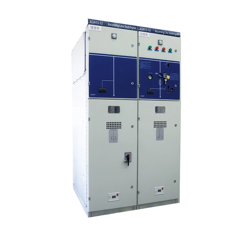


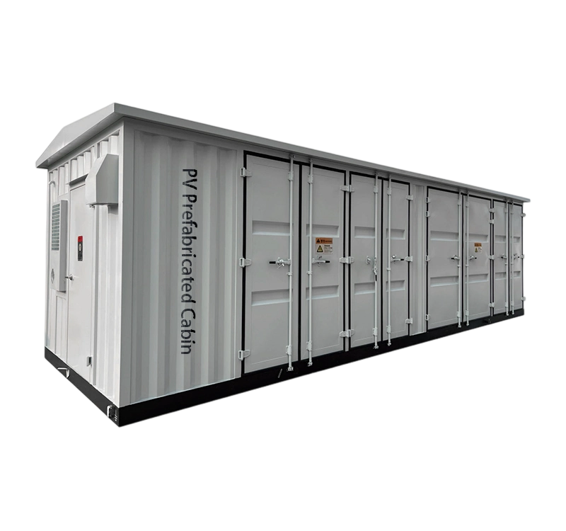
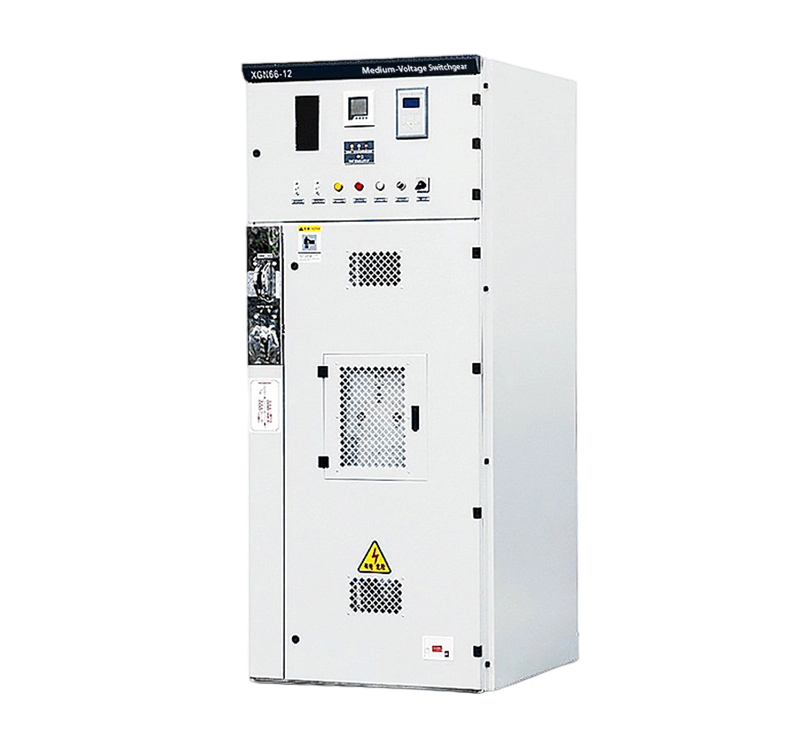
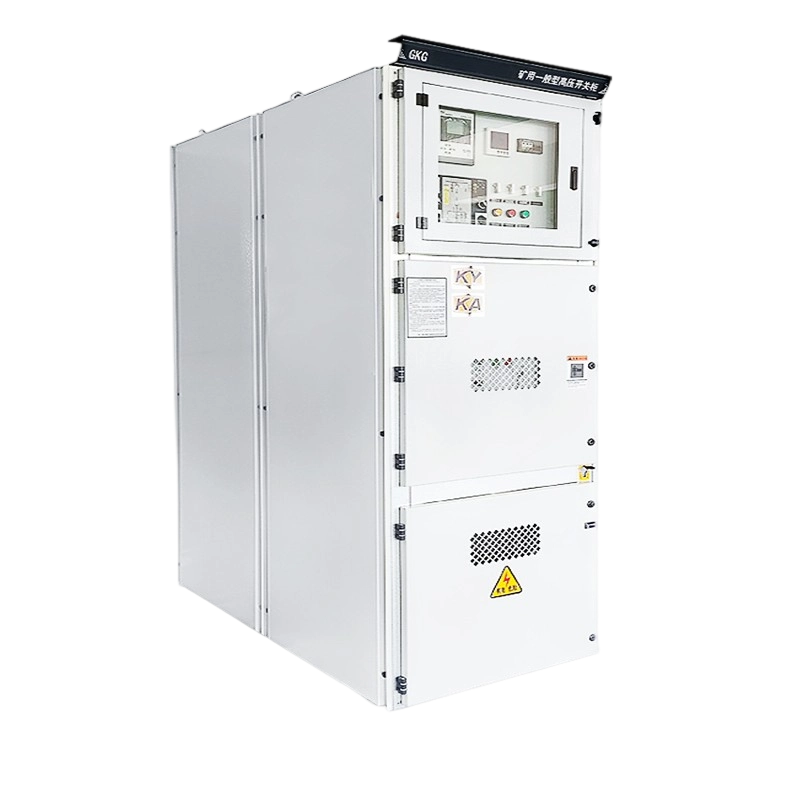
11kV is a very common voltage level in medium-voltage (MV) distribution systems. 11kV switchgear is a core component of power transmission and distribution networks, used for receiving, distributing, controlling, protecting, and monitoring electrical energy.

I. Primary Functions
Isolation: Provides visible and reliable electrical isolation points during equipment maintenance to ensure personnel safety.
Protection: Rapidly interrupts fault currents (short-circuit, overload, earth fault) to protect upstream sources and downstream equipment.
Control: Connects or disconnects normal load currents for circuit switching operations.
Measurement: Displays parameters like voltage, current, and power via instruments.
Monitoring: Provides status indications (e.g., circuit-breaker position, earthing switch position, spring charging state).
Metering (Optional): Provides signals for energy metering.
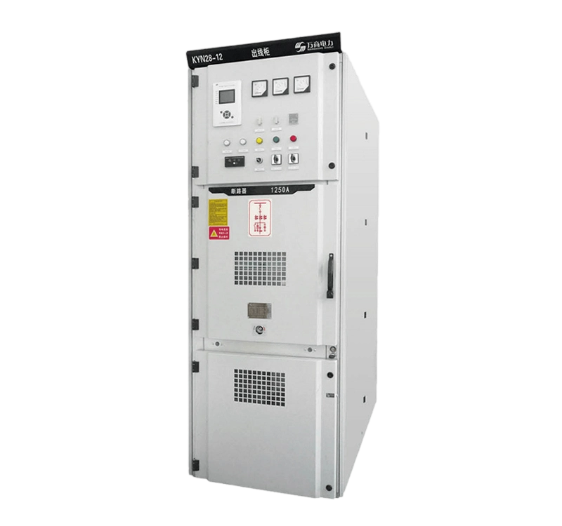
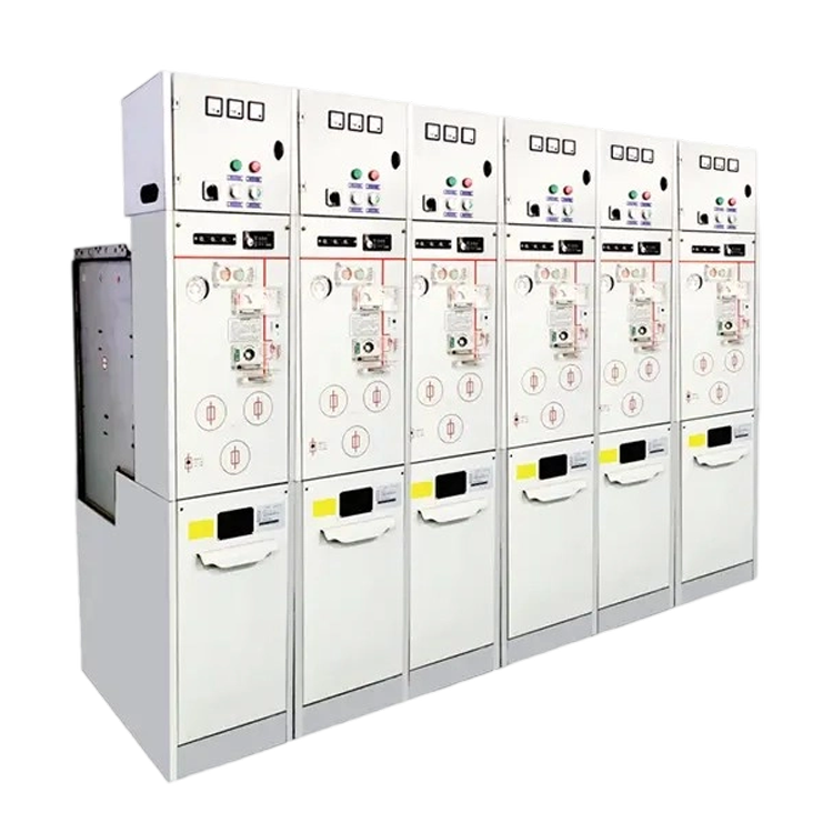
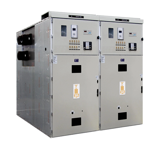
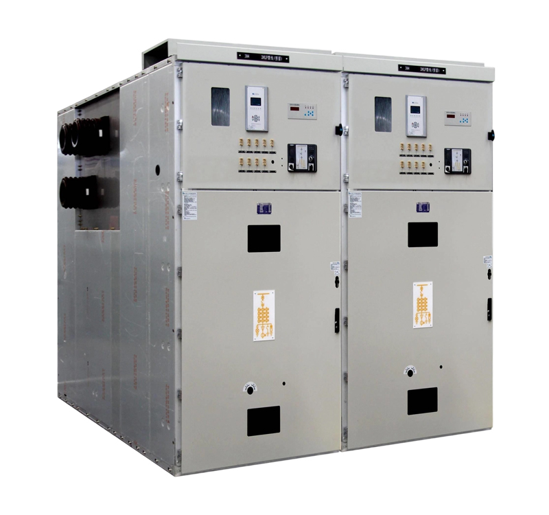
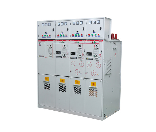
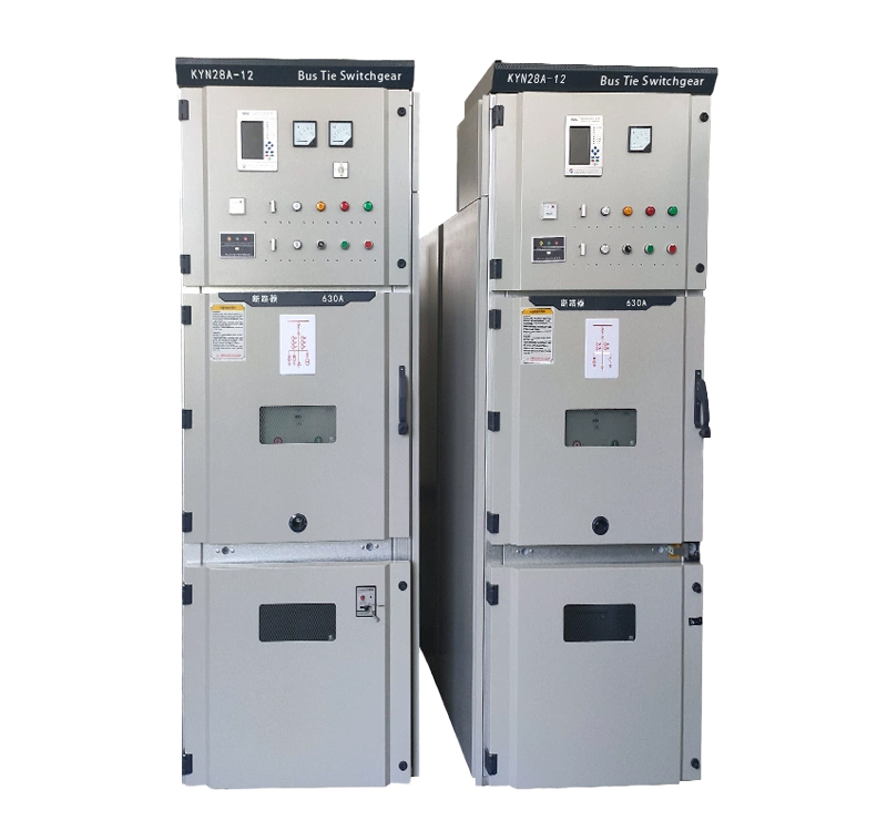
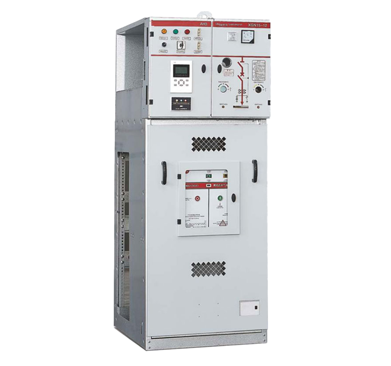
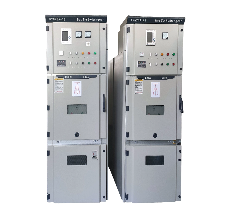
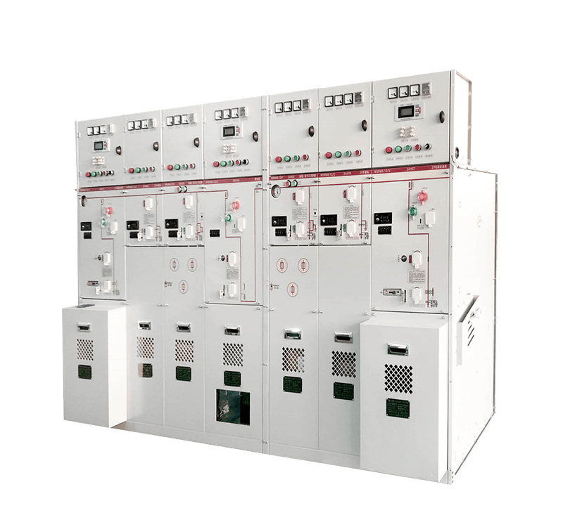
II. Typical Structure (Example: Withdrawable Metal-Clad Switchgear)
Modern 11kV switchgear typically features modular, metal-enclosed, metal-clad designs for high safety and reliability. Its main components are divided into segregated compartments, usually separated by metal barriers, fulfilling “Five Safety Interlock” requirements:
Enclosure and Frame:
Constructed from high-quality steel plate (e.g., Aluzinc) welded or assembled, providing mechanical support and protection.
Meets specified Ingress Protection (IP) rating (e.g., IP4X).
Entire cubicle is reliably earthed for operator safety.
Circuit-Breaker Compartment:
Core Component: The Vacuum Circuit-Breaker (VCB) is the primary interrupting device. Mounted on a withdrawable carriage (truck).
Withdrawable Carriage (Truck): The VCB is fixed to the carriage, which can be moved between “Service (Connected) Position,” “Test/Disconnected Position,” and “Withdrawn (Removed) Position.” In Service Position, the main circuit is connected. In Test Position, the main circuit is isolated, but the secondary control circuits remain connected for open/close testing. In Withdrawn Position, the carriage can be fully extracted for maintenance.
Arc-Quenching Medium: Utilizes vacuum interrupters, offering high breaking capacity, long life, minimal maintenance, and environmental benefits (no SF6).
Operating Mechanism: Typically a spring-operated mechanism. Can be charged electrically/manually, and opened/closed electrically/manually. Charging state is clearly indicated.
Primary Contacts: The VCB’s moving contacts engage with fixed female contacts (finger cluster contacts) mounted in the compartment. The carriage movement connects/disconnects the main circuit via these primary isolating contacts.
Busbar Compartment:
Located at the top or rear-upper part of the cubicle.
Main Components: Main busbars and branch busbars (for inter-cubicle connection).
Material: Usually copper bars (rectangular or round), potentially tin or silver-plated.
Insulation: Busbars are supported and insulated from earth and each other by insulators (bushings or post insulators) fixed to metal barriers.
Connection: Main busbars run through all cubicles, connected via busbar connectors.
Cable Compartment (Outgoing Feeder Compartment):
Located at the bottom or rear-lower part of the cubicle.
Function: Connects to outgoing cables feeding transformers or loads.
Main Components:
Cable Terminations: Connect to HV cables.
Current Transformers (CTs): Typically installed here for current measurement and protection signaling.
Earthing Switch (ES): Used to earth the outgoing cable side during maintenance.
Surge Arresters (Lightning Arresters – LA): Limit switching and lightning overvoltages, protecting equipment insulation.
Voltage Presence Indicators (VPIs): Visually indicate line voltage presence.
Space: Ample space is provided for cable installation, termination, and maintenance.
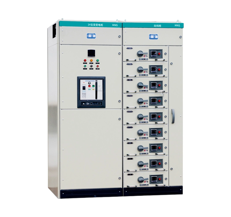
Instrument & Relay Compartment (Low-Voltage Compartment / Secondary Compartment):
Located at the front-upper or central part of the cubicle, often with a separate door.
Function: Houses low-voltage (LV) secondary equipment for control, protection, measurement, signaling, and metering.
Main Components:
Protection Relay / Microprocessor-Based Relay: The intelligent unit performing protection functions (overcurrent, short-circuit, earth fault, overload) based on CT/VT signals, issuing trip/close commands.
Instruments: Ammeters, voltmeters, wattmeters, power factor meters.
Indicating Lights (Lamps): Circuit-breaker ON/OFF position, spring charged/discharged, earthing switch ON/OFF, carriage position, fault indication.
Control Switches / Pushbuttons: Local open/close buttons, Remote/Local selector switch.
Terminal Blocks: Connect internal secondary devices to external control wiring.
VT Secondary Fuses or Miniature Circuit-Breakers (MCBs): Protect secondary circuits.
(Optional) Energy Meter: For metering.
DC Power Supply: Provides operating power (typically DC 110V or DC 220V) for relays, trip/close coils.
This compartment requires dust and moisture protection, usually with a higher IP rating (e.g., IP3X).
Disconnector / Earthing Switch Compartment (Often associated with CB or Cable Compartment):
Disconnector (Isolator): Fixed designs may require separate disconnectors for isolation. In withdrawable designs, the carriage movement provides main circuit isolation, but maintenance earthing switches might be present.
Earthing Switches (ES):
Cable Side Earthing Switch: Mounted in the cable compartment for earthing the outgoing cable side.
Busbar Side Earthing Switch: Sometimes located below the CB or busbar compartment for earthing the busbar or cable side during CB maintenance (requires strict interlocking).
Operating mechanisms are usually manual (crank handle or lever), with clear position indication and mechanical interlocks.
III. Core Operating Principles
Normal Closing (Energizing):
CB carriage is racked into “Service Position,” primary isolating contacts close reliably.
Close command issued via control circuit (local button or remote signal).
Protection relay (if enabled) outputs no blocking signal.
CB operating mechanism’s closing coil energizes (or releases stored spring energy), driving the vacuum interrupter moving contacts to close rapidly.
Main circuit connects. Current Path: Main Busbar -> Upper Fixed Contacts -> CB Main Contacts -> Lower Fixed Contacts -> CTs -> Outgoing Cable -> Load.
“CB Closed” indicator illuminates.
Normal Opening (De-energizing):
Open command issued via control circuit.
CB operating mechanism’s tripping coil energizes (or triggers the trip release), driving the vacuum interrupter moving contacts to separate rapidly.
An arc forms momentarily upon separation and is rapidly quenched by the high dielectric strength of the vacuum.
Main circuit is reliably interrupted.
“CB Open” indicator illuminates.
Protective Tripping (Fault Clearing):
When a fault (short-circuit, overload, earth fault) occurs downstream, CTs detect the abnormal high current.
CT secondary circuits feed a proportional replica of the fault current to the protection relay.
The relay compares the measured current against preset protection settings (e.g., instantaneous overcurrent, time-delayed overcurrent, time delays) and logic.
If the fault current exceeds the setting and the time condition is met, the relay operates, closing its output contact.
This contact energizes the CB operating mechanism’s tripping coil circuit.
The CB trips rapidly, interrupting the fault current and preventing damage propagation.
The relay generates a fault alarm signal (light, sound, communication message).
Maintenance Isolation & Earthing:
Rack CB carriage to “Test Position” or “Withdrawn Position,” disconnecting the primary isolating contacts to create a visible isolation gap.
Verify Dead: Confirm the cable side is de-energized using VPIs or a voltage detector.
Operate Earthing Switch: Close the cable side earthing switch, reliably earthing any potentially back-fed cable circuits to protect maintenance personnel. Some designs include busbar side maintenance earthing switches (requires strict interlocking).
The circuit is now isolated and safely earthed, allowing maintenance.
IV. Summary
11kV switchgear is a highly integrated, safe, and reliable assembly incorporating HV switching devices (circuit-breaker, disconnectors, earthing switches), measuring devices (CTs, VTs), protection devices (relays), control equipment, and busbar systems. Its core function is current interruption using a vacuum circuit-breaker, underpinned by precise mechanical structures and the “Five Safety” interlocking system to ensure all operations (especially isolation and earthing) strictly follow safety protocols. This enables safe, reliable, and flexible control, protection, and monitoring of MV power systems. Understanding its compartmentalized structure, component functions, and the principles of CB operation, fault protection, and maintenance isolation/earthing is key to mastering and applying 11kV switchgear.


.png)