I. Working Principle
The core principle of rotor earth fault protection is to monitor the insulation condition of the generator’s field circuit (rotor circuit) to ground. Under normal conditions, the rotor circuit is insulated from ground, with only a very small leakage current to earth. A single earth fault does not create a short-circuit path (as a return path is missing), but it serves as a critical alarm because a subsequent second earth fault would have severe consequences.
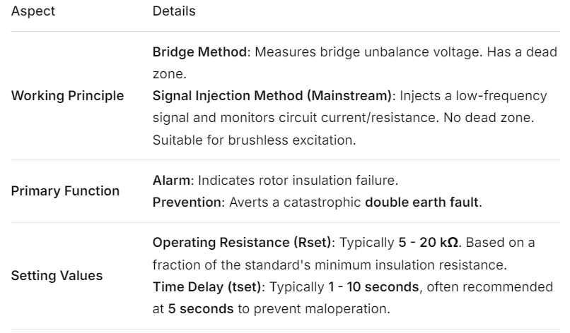
Two main protection principles are prevalent: the Bridge Method and the Signal Injection Method.
1. Bridge Method (Traditional Principle)
This method is primarily used for generators with brushes that provide access to the field circuit, such as many hydro generators.
Configuration: The protection device contains an internal Wheatstone bridge. Two arms are fixed resistors (R1, R2), and the other two arms are the resistances from the positive (R+) and negative (R-) sides of the rotor winding to ground.
Normal Operation: When rotor insulation is healthy, both R+ and R- are very high and approximately equal. The bridge is balanced, the voltage at the measuring point (M) is zero or minimal, and the protection does not operate.
Single Earth Fault Occurrence: If an earth fault occurs at point K, the value of R+ decreases (becoming the winding resistance from the fault point to the positive terminal), while R- increases. This unbalances the bridge, producing a voltage at the measuring point M. If this voltage exceeds the set threshold, the protection device issues a “Rotor Earth Fault” alarm.
Disadvantages:
Dead Zone: If the fault occurs near the electrical center of the rotor winding, the bridge may remain balanced, causing protection failure.
Requires brushes for access to the field circuit, making it unsuitable for brushless excitation systems.
Performance is affected by variations in the field voltage.
2. Signal Injection Method (Modern Standard)
This method works by injecting a specific frequency AC voltage signal into the rotor circuit to monitor its insulation to ground. It is suitable for all generator types, especially brushless excitation systems.
Configuration: The protection device contains a voltage source (typically a low-frequency AC signal, e.g., 12.5 Hz, or a square wave) which is injected via a coupling capacitor C between the field circuit and the rotor body (ground).
Normal Operation: When rotor insulation is healthy, the ground insulation resistance (Rg) is very high, resulting in a very small current in the injection circuit.
Single Earth Fault Occurrence: When an earth fault occurs, Rg drops drastically, creating a complete circuit for the injected signal. The resulting current increases significantly. The protection device measures this current (or a related voltage) to calculate the real-time ground insulation resistance Rg.
Operating Criterion: The protection operates when the calculated ground resistance meets: Rg ≤ Setting Value.
Advantages:
No Dead Zone: It can operate sensitively regardless of the fault location along the rotor winding.
Safe and Reliable: The injected voltage is low (typically <50V) and low-power, preventing damage to rotor insulation.
Measures Insulation Resistance: It can display the real-time ground insulation resistance value, aiding maintenance personnel.
Suitable for Brushless Systems: It only requires a connection (via brushes or a coupling capacitor) to the rotor shaft.
2. Signal Injection Method (Modern Standard)
1.This method works by injecting a specific frequency AC voltage signal into the rotor circuit to monitor its insulation to ground. It is suitable for all generator types, especially brushless excitation systems.
2.Configuration: The protection device contains a voltage source (typically a low-frequency AC signal, e.g., 12.5 Hz, or a square wave) which is injected via a coupling capacitor C between the field circuit and the rotor body (ground).
Normal Operation: When rotor insulation is healthy, the ground insulation resistance (Rg) is very high, resulting in a very small current in the injection circuit.
Single Earth Fault Occurrence: When an earth fault occurs, Rg drops drastically, creating a complete circuit for the injected signal. The resulting current increases significantly. The protection device measures this current (or a related voltage) to calculate the real-time ground insulation resistance Rg.
Operating Criterion: The protection operates when the calculated ground resistance meets: Rg ≤ Setting Value.
Advantages:
No Dead Zone: It can operate sensitively regardless of the fault location along the rotor winding.
Safe and Reliable: The injected voltage is low (typically <50V) and low-power, preventing damage to rotor insulation.
Measures Insulation Resistance: It can display the real-time ground insulation resistance value, aiding maintenance personnel.
Suitable for Brushless Systems: It only requires a connection (via brushes or a coupling capacitor) to the rotor shaft.
II. Function
1.Issue an Alarm Signal: This is its primary function. Upon detecting a single earth fault, the protection immediately issues an audible and visual alarm, alerting operators that the rotor circuit insulation has failed.
2.Prevent a Second Earth Fault: A single earth fault is not critical by itself, as no significant fault current flows. The danger lies in a subsequent second earth fault, which creates a short-circuit path through the rotor.
Hazards of a Second Earth Fault:
Damage to Rotor Winding and Core: A portion of the rotor winding is short-circuited, carrying very high current, which generates extreme local heating, destroying insulation and conductors.
Severe Vibration: The magnetic field symmetry is disrupted, creating an unbalanced magnetic pull. This causes severe mechanical vibration, potentially damaging bearings and the foundation.
Magnetic Circuit Unbalance: Can distort the air-gap magnetic flux, affecting generator output.
Shaft Damage: High fault currents can arc and damage the turbine shaft.
Enable Scheduled Outage for Repair: The alarm allows operators to plan and schedule a unit shutdown for inspection and repair at a convenient time, preventing a forced outage and catastrophic failure.
III. Setting Value Calculation
The goal of setting calculation is to ensure reliable operation without false tripping, while being sensitive enough to detect deteriorating rotor insulation.
For the mainstream Signal Injection Rotor Earth Fault Protection, the primary settings are the Operational Resistance Value and the Time Delay.
1. Operating Resistance Setting (Rset)
Basic Principle:
Must be above the maximum measured ground insulation resistance during normal operation.
Must be below the minimum allowable insulation resistance specified by standards.
Calculation Method:
Typically set using empirical formulas and standards:
Rset = (0.5 ~ 0.8) × (Minimum Allowable Insulation Resistance per Standard)
Minimum Allowable Insulation Resistance: According to standards like IEEE C37.102 or equivalent guides, the rotor winding insulation resistance should not fall below 0.5 MΩ (under hot conditions, e.g., 75°C).
Reliability Factor: The factor of 0.5 to 0.8 ensures the protection operates reliably before the insulation resistance decays to a dangerous level, providing a safety margin.
Typical Setting Range:
Consequently, the typical operating resistance setting in practice is: Rset = 5 kΩ to 20 kΩ
Example: Using 0.6 times the standard value gives Rset = 0.6 × 0.5 MΩ = 0.3 MΩ = 300 kΩ. However, for higher sensitivity, it is often set lower, such as 10 kΩ. The final value should be fine-tuned based on the specific unit’s history and operational experience.
2. Operating Time Delay Setting (tset)
Purpose: To prevent false operation due to transient conditions (e.g., momentary insulation drop caused by oil or moisture).
Setting Principle:
A genuine earth fault is typically a permanent, not transient, condition.
The delay must be long enough to ride through disturbances but short enough to alarm promptly before a second fault might occur.
Typical Setting Value:tset = 1 to 10 seconds
A setting of 5 seconds is commonly recommended. This is sufficient to override most transient disturbances while ensuring timely alarm.
Summary
In practice, the Signal Injection Method is the absolute standard due to its superior performance.The final determination of setting values must consider the generator’s specific design, excitation system, and operational history, following the relevant protection engineering guides.