Transformer Magnetizing Inrush Current: Definition and Significance
- Definition: Transient phenomenon during transformer noload energization or voltage recovery postfault.
- Core Saturation Effect: Nonperiodic surge current (68× rated current) with rapid decay under saturated core conditions.
- Protection Significance: Critical to prevent differential protection maloperation and mitigate mechanical stress risks.
1. Fundamental Causes: Saturation Physics and Switching Dynamics
- Core Saturation Mechanism: Nonlinear BH curve of ferromagnetic materials → beyond Bsat, μ ≈ μ₀ requires excessive current for flux increase.
- Remanence Influence: Residual flux (Br) polarity/magnitude determined by deenergization state.
- ZeroCrossing Trigger: Closing at voltage phase 0°/180° maximizes inrush magnitude.
- Flux Composition Analysis:
-
- Steadystate flux Φs(t) = (Um/N₁ω)cos(ωt+θ)
- Initial condition: Φ(0) = Br (Faraday’s Law)
- Total flux = Free Component [Br – Φs(0)]e–Rt/L + Forced Component Φs(t)
-
-
- Peak Saturation Scenario: Worstcase closing (θ=0°/180°+aligned Br) → flux peak > Bsat at ωt=π.
- Inrush Generation Principle: Current surge proportional to saturation slope when flux exceeds Bsat.
2. Key Characteristics: Waveform Signature and Harmonic Behavior
- High Magnitude Trait: 68× rated current (variables: closing angle, Br, system impedance).
- DC Offset Nature: Asymmetric waveform with exponential decay envelope.
- Distinct Waveform Features:
-
- Dead angle manifestation near zerocrossings
- Peaked shape with notches during decay phase
-
-
- Harmonic Dominance: 2nd harmonic content (2060%) as key fault discriminator.
- Decay Time Constant: Duration governed by L/R ratio (slower in large transformers).
- Phase Asymmetry Consequence: Nonsimultaneous closing + 120° phase shift → differential protection unbalance.
3. System Impacts: Protection Challenges and Mechanical Risks
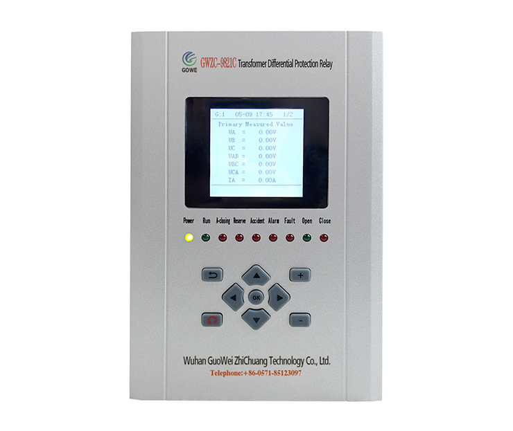
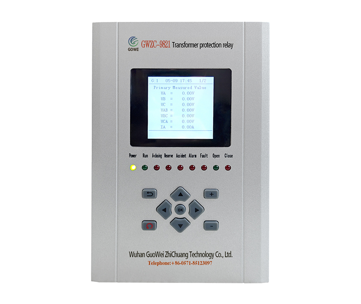
- Protection Interference Risk: False trips in Transformer Differential Protection Relays.
- Mechanical Stress Hazard: Electrodynamic forces potentially causing winding deformation (critical for aged units).
- Power System Consequences:
-
- Transient voltage sags during energization
- Harmonic pollution affecting sensitive loads
- Circuit breaker prestrike damage potential
4. Mitigation Strategies: Harmonic Restraint and Controlled Switching
WaveformBased Restraint Methods:
- Second harmonic restraint (industry standard)
- Dead angle discrimination algorithms
- Waveform asymmetry analysis
Advanced Switching Techniques:
- Pointonwave closing at voltage peak
- Preinsertion resistor current limiting
Supplementary Solutions:
- Predemagnetization for residual flux compensation
- TPYclass CTs for antisaturation performance
5. Conclusion: Operational Importance and Technical Solutions
- Transient Origin Synthesis: Inherent phenomenon from core saturation nonlinearity, remanence effects, and precise switching timing.
- Critical Waveform Identifiers: High magnitude, dead angle, and 2nd harmonic dominance.
- Operational Risks: Mechanical stress accumulation and protection system maloperation.
- Resolution Framework: Reliability achieved through harmonic restraint algorithms combined with pointonwave switching technology.

