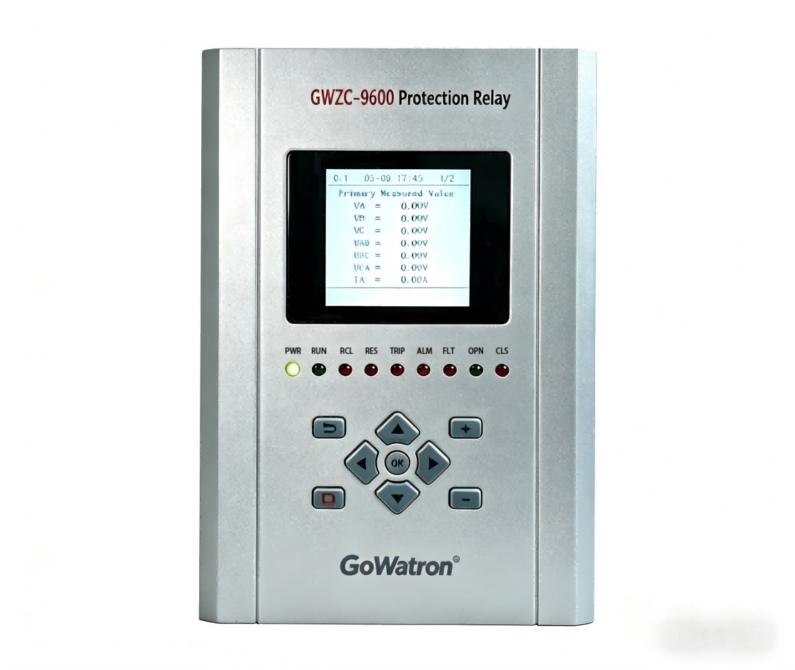
The Transformer Differential Protection Relay is a primary protection for power transformers. Its universal ANSI/IEEE device function number is 87T.
I. Transformer Differential Protection /Working Principle
The working principle of the Transformer Differential Protection Relay is based on Kirchhoff’s Current Law. This law states that the sum of currents entering a node is zero. Ideally, for a healthy (non-faulted) transformer, the current entering the primary winding should equal the current leaving the secondary winding (after accounting for the transformer’s turns ratio and phase shift).
1. Core Concepts:
Differential Current (Operate Current): The vector sum of the currents entering all terminals of the protected transformer zone.
Restraining Current (Restrain Current): A measure, often the scalar sum or a maximum value, of the currents used to bias the relay and prevent operation during external faults or normal load conditions.
2. System Configuration:
The protection system consists of Current Transformers installed on all sides of the transformer (e.g., High Voltage HV and Low Voltage LV sides) and the Transformer Differential Protection Relay itself. The CT polarities must be oriented towards the transformer to ensure correct current direction measurement.
3. Operating Logic:
During Normal Load or External Faults:
Although the magnitude and phase of the currents on the transformer’s different sides are different, after internal compensation within the relay (for ratio and phase angle), their vector sum is theoretically zero.
In this condition, the Differential Current ≈ 0, while the Restraining Current is significant.
Since the differential current is much smaller than the restraining current, the relay does not operate.
During Internal Faults:
The fault point creates an additional fault current supplied from all sides of the transformer.
This disturbs the balance between the currents entering and leaving the transformer zone, causing the vector sum (the differential current) to become significantly large.
In this condition, the Differential Current >> 0.
When the differential current exceeds the set threshold and satisfies the operating characteristic curve, the relay identifies an internal fault and issues a trip command.
4.Challenges to Overcome:
In practice, the following factors can cause a “spurious” differential current under non-fault conditions, which the relay must discriminate against and restrain:
CT Errors and Saturation: CTs may saturate, especially during external faults, causing distortion of their secondary current.
Transformer Magnetizing Inrush Current: When a transformer is energized, it can draw a large, harmonic-rich magnetizing current.
Transformer Tap Changer Operation: Changes the actual transformer ratio, disrupting the balance of the CT secondary currents.
Modern digital differential protection relays address these issues by employing a Percentage Restraint Characteristic (Ratio Differential Characteristic) supplemented by Harmonic Restraint.
A typical percentage restraint characteristic curve is illustrated below:
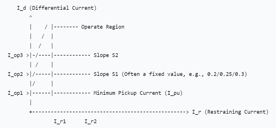
Characteristic Curve Explanation:
Minimum Pickup Current (I_pu): The threshold value; the protection can only operate if the differential current exceeds this value.
Percentage Restraint Region: The operate current threshold increases as the restraining current increases. This ensures that during external faults (high restraining current), the protection remains stable even if some differential current exists due to CT errors.
Harmonic Restraint: The relay analyzes the harmonic content of the differential current. Magnetizing inrush current contains a high percentage of second harmonic. If the second harmonic content exceeds a set value (typically 15%-20%), the relay blocks the differential protection to prevent maloperation.
II. Transformer Differential Protection /Functions
The primary functions of the Transformer Differential Protection Relay are:
Rapid Isolation of Internal Faults: Acting as the primary protection, it detects and clears various internal faults within the transformer windings, leads, and bushings, such as phase-to-phase faults, turn-to-turn faults, and ground faults, with high sensitivity and speed.
Prevention of Fault Escalation: By rapidly isolating the faulted equipment, it prevents the fault from developing further, which could cause catastrophic damage to the core asset and maintains stability for the rest of the power system.z
Improved System Reliability: By selectively isolating only the faulted transformer, it minimizes the extent of the power outage.
III. Transformer Differential Protection /Setting Calculation
Setting calculations are critical to ensure the correct and reliable operation of the protection relay. The following outlines the calculation steps and considerations for key settings. Please note that specific formulas and recommended values may vary slightly depending on the relay manufacturer and applicable engineering standards; the following provides general principles.
Basic Parameter Definitions:
I_transformer: Rated current of the transformer
I_ct: Rated secondary current of the CT (typically 1A or 5A)
n: Transformer ratio compensation factor (handled by relay software)
I_diff: Differential Current
I_rest: Restraining Current
Step 1: Calculate Rated Currents and CT Secondary Currents
Calculate the rated current for each side of the transformer (HV, LV) and refer them to the CT secondary side.
I_sec = I_transformer / I_ct
Step 2: Determine the Minimum Pickup Current
This setting is used to override the maximum steady-state unbalanced current during normal transformer operation (caused by CT errors and tap changer operation).
Formula: I_op1 = k * I_transformer
Where:
I_op1 is the Minimum Pickup Current (also called I_pu), typically expressed as a multiple of the transformer’s rated current.
k is a reliability factor, typically between 0.2 and 0.5. For modern digital relays, 0.2 or 0.3 is common.
Step 3: Determine the Initial Restraint Slope
This slope is used to override the unbalanced current under light external fault or load conditions.
Formula: S1 = k1
Where:
S1 is the Initial Restraint Slope.
k1 is the slope percentage, typically set between 0.15 and 0.30 (i.e., 15% to 30%). A common setting is 0.25 or 25%.
Step 4: Determine the Maximum Restraint Slope
This slope ensures stability during severe external faults where CT saturation is likely.
Formula: S2 = k2
Where:
S2 is the Maximum Restraint Slope.
k2 is the slope percentage, typically set between 0.50 and 0.80 (i.e., 50% to 80%). A common setting is 0.60 or 60%.
The breakpoint I_r2 is typically set above 5-10 times the rated current.
Step 5: Harmonic Restraint Settings
Used to discriminate against magnetizing inrush current.
2nd Harmonic Restraint: Typically set to block the protection when the ratio of the second harmonic component to the fundamental component in the differential current exceeds a threshold.
Setting Range: Typically 15% to 20%.
5th Harmonic Restraint: Used to identify transformer over-fluxing conditions. Typically set between 30% and 40%.
Step 6: Instantaneous Differential Element
This is an unrestrained, high-set differential element for high-speed clearing of severe internal faults.
Formula: I_inst = k_inst * I_transformer
Where:
I_inst is the Instantaneous Differential pickup value.
k_inst is a multiplier, typically set between 8 and 12 times the rated current to override the maximum possible magnetizing inrush current.
Calculation Example (Simplified):
Assume a transformer with a rated current of 1000A, and CT ratio of 1000/5A.
CT Secondary Rated Current: 1000A / (1000/5) = 5A
Minimum Pickup Current I_op1: Using k=0.3, I_op1 = 0.3 * 5A = 1.5A (relay setting value).
Initial Restraint Slope S1: Set to 0.25 or 25%.
Maximum Restraint Slope S2: Set to 0.60 or 60%, with breakpoint I_r2 set to 5 * 5A = 25A.
2nd Harmonic Restraint: Set to 18%.
Instantaneous Differential: Using k_inst=10, I_inst = 10 * 5A = 50A.
Important Note:
Final settings must be determined through comprehensive system studies, considering all possible operating conditions and fault types. The calculations above are for general guidance only. In practical engineering applications, it is imperative to consult the technical manual of the specific protection relay being used and the relevant industry standards.
Our company is a professional manufacturer of transformer protection relays. If you have any needs, please feel free to contact us. We will provide you with comprehensive services!