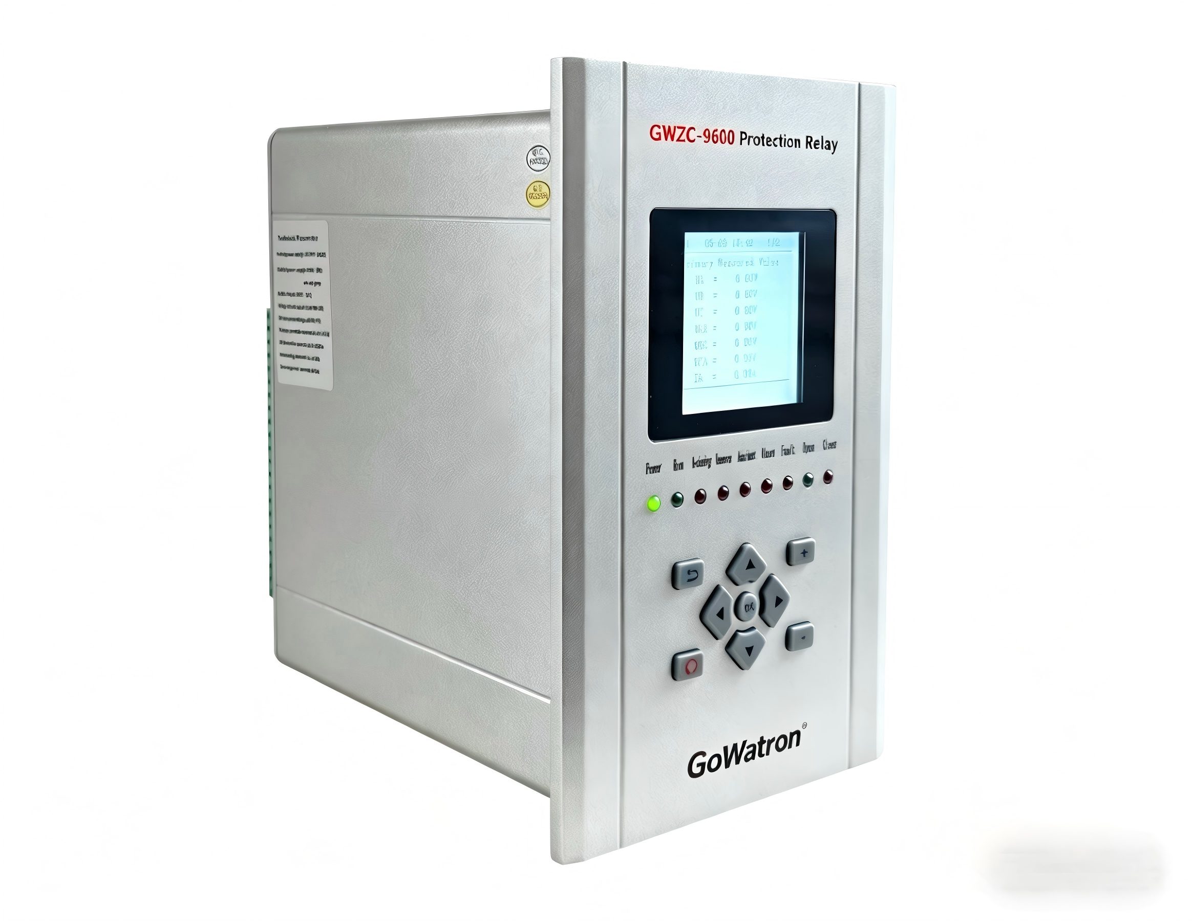
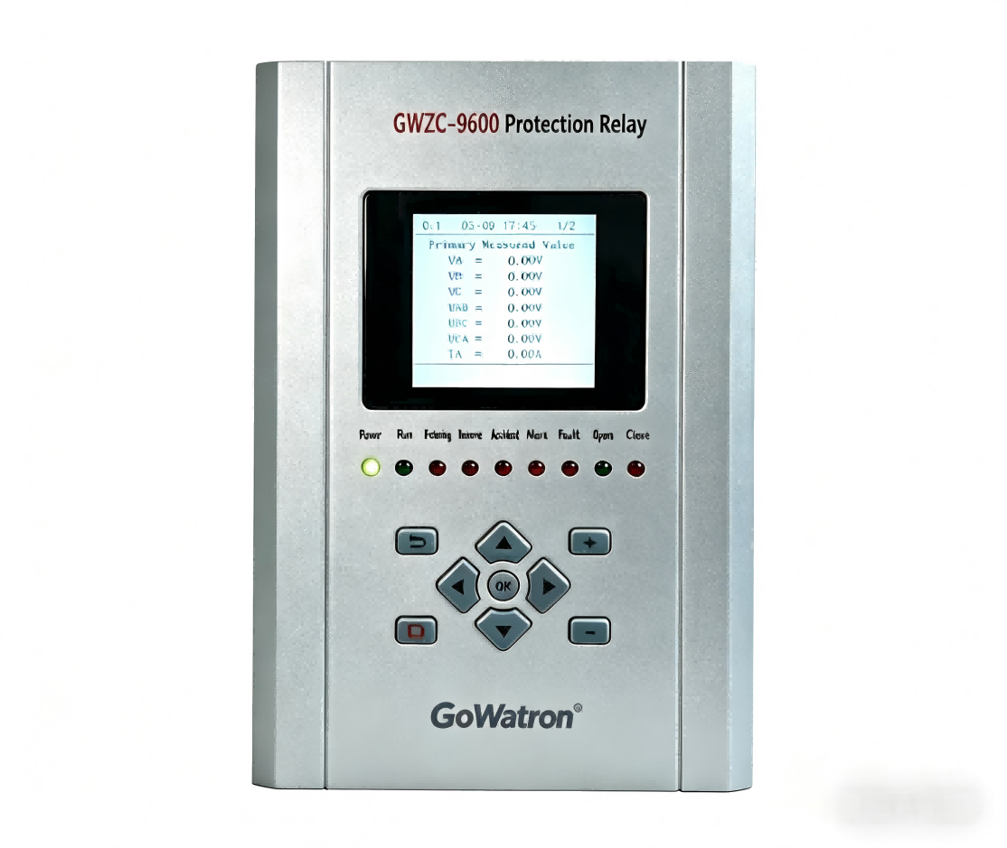
1. Introduction to Thermistor Motor Protection Relay
Thermistor Motor Protection Relay monitors motor winding temperature in real-time using PTC/NTC thermistors, triggering protection (alarm or power cutoff) against overheating. It is suitable for critical equipment like servo and high-voltage motors, effectively preventing insulation damage and burnout failures.
Function: Monitors motor winding temperature to prevent insulation damage or burnout due to overheating.
Scope of Application : Suitable for AC/DC motors (e.g., servo motors, inverter-driven motors, high-voltage motors), especially for high-value or continuously operated equipment.
Key Features:
Real-time temperature detection via PTC (Positive Temperature Coefficient) or NTC (Negative Temperature Coefficient) thermistors.
Triggers alarms or cuts off power to protect the motor from thermal damage.
2. Working Principle of Thermistor Motor Protection Relay
2.1 Types of Thermistors
PTC: Resistance increases sharply with temperature rise .
NTC: Resistance decreases with temperature rise.
2.2 Operation Process
Thermistor Integration: Embedded in motor windings, resistance changes with temperature.
Threshold Detection: The relay monitors resistance; if it exceeds the set limit (e.g., PTC trip resistance typically 3–4 kΩ), it triggers a trip signal.
Protective Action: Relay output contacts either disconnect the motor power supply or send an alarm signal.
Formula Reference:
PTC resistance-temperature relationship (example):
R(T)=R 0⋅ e B(T−T 0 )
(where R 0 = baseline resistance, B = material constant)
3. Application Scope of Thermistor Motor Protection Relay
3.1 Suitable Scenarios
Motors with frequent start-stop cycles or heavy loads (e.g., cranes, compressors).
High ambient temperatures or poor cooling conditions.
3.2 Limitations
Not applicable for motors without built-in thermistors (requires external sensor installation).
4. Functions and Features of Thermistor Motor Protection Relay
4.1 Core Protection Functions
Overload Warning: Early alarm to prevent sudden failure.
Direct Trip: Prevents thermal breakdown of insulation.
4.2 Advanced Features (High-End Models)
Temperature trend logging, communication interfaces (Modbus/Profibus).
5. Practical Solutions for Thermistor Motor Protection Relay
5.1 Selection Guide
Thermistor Type: Must match the motor’s built-in sensor (PTC/NTC).
Threshold Setting: Based on motor insulation class (e.g., Class B ≤ 130°C, Class F ≤ 155°C).
Relay Output Options:
Dry Contact: Directly controls the contactor.
Active Signal: Connects to PLC for remote monitoring.
5.2 Troubleshooting Guide
False Tripping: Check for loose or shorted thermistor wiring.
No Response: Test resistance at room temperature (PTC should be ~50–100Ω).
6. Safety Guidelines for Thermistor Motor Protection Relay
6.1 Installation Precautions
Power Off & Voltage Check: Verify no voltage using a multimeter before installation.
Wiring Separation: Avoid running thermistor wires parallel to power cables (prevents interference).
6.2 Maintenance Best Practices
Annual Calibration: Compare against a standard temperature source.
7. Example Application of Thermistor Motor Protection Relay
A plastic injection molding machine motor overheated due to a cooling fan failure. The PTC thermistor triggered the relay at 140°C, cutting power and preventing winding burnout. Post-inspection revealed a loose fan power connection; after repair, the relay was reset, and the motor resumed normal operation.