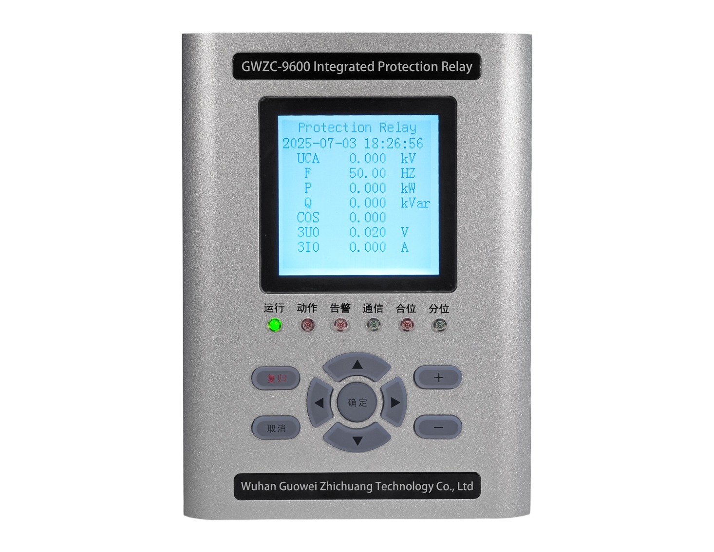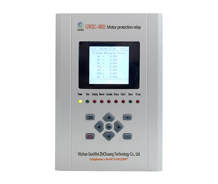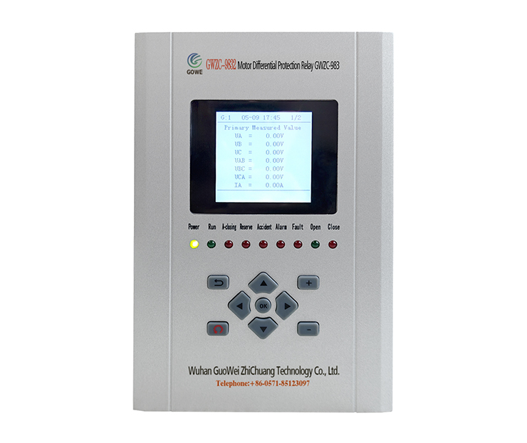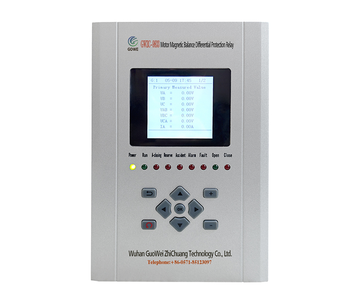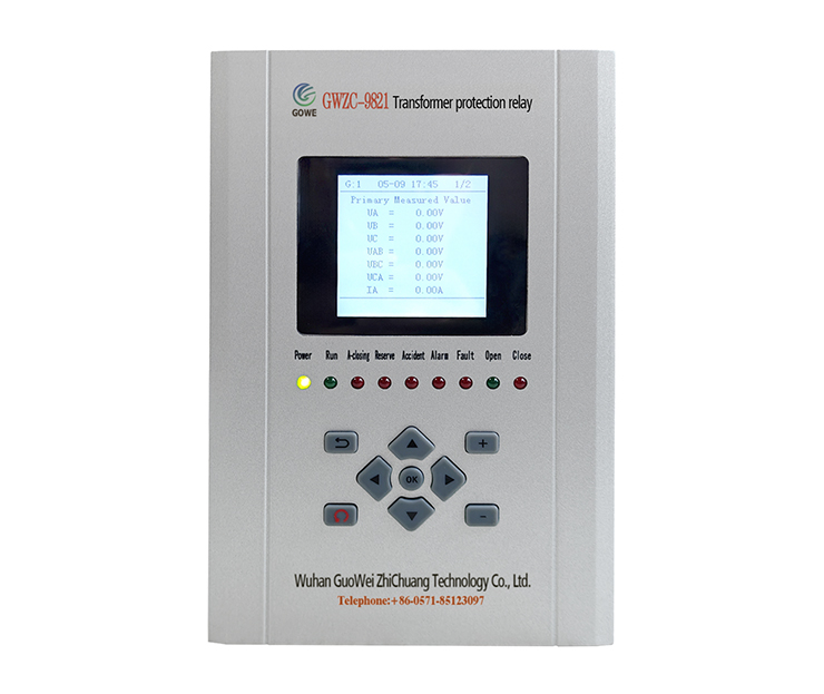
Introduction to Motor Stall Protection
Motor stall protection is a mechanism designed to prevent motor damage from overheating due to sustained stall currents caused by excessive load or mechanical jamming. During stalling, motor current surges rapidly. Failure to promptly cut off power may result in burnt windings or equipment damage. This protection rapidly activates by monitoring parameters such as current, temperature, or rotational speed upon stalling, either disconnecting power or triggering alarms to ensure motor safety and extend equipment lifespan.
Role of Motor Stall Protection
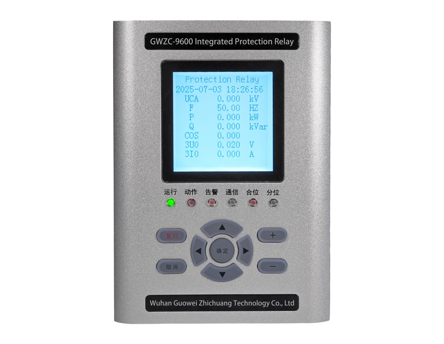
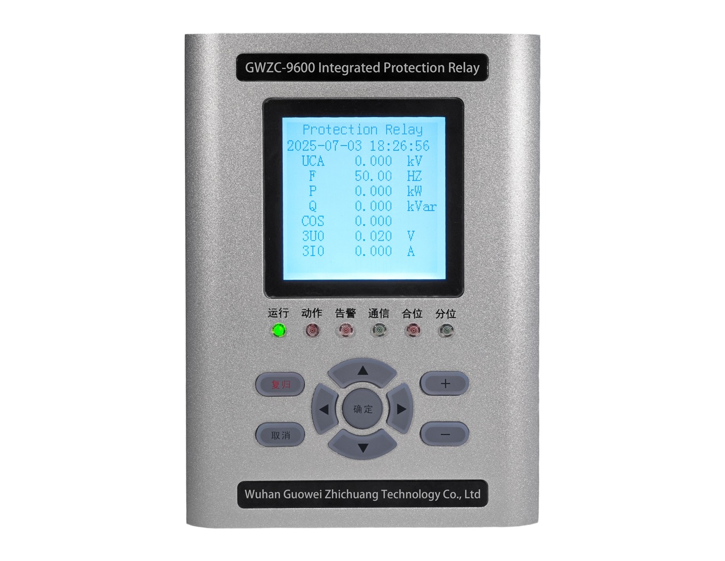
The core function of stall protection is to prevent severe accidents caused by motor stalling due to mechanical obstruction, overload, or power supply abnormalities. During stalling, current can reach 5-7 times the rated value, rapidly generating high temperatures that damage insulation or burn coils. The moter protection relay promptly cuts off the circuit, preventing motor overheating fires, mechanical deformation, or collateral damage to drive systems. This ensures production safety, reduces downtime and maintenance costs, and is suitable for applications like fans, pumps, and conveyor systems.
Functions of Motor Stall Protection
1. Current Monitoring: Real-time detection of motor current to identify stall characteristics (e.g., sudden current increase).
2. Fast Tripping: Power cutoff or alarm triggering within set time limits.
3. Time-Delayed Protection: Distinguishes starting current from stall current to prevent false trips.
4. Temperature Compensation: Dual protection through integration with thermal elements.
5. Fault Recording: Stores stall event data for failure analysis. Advanced protections may include auto-reset or remote notification.
Principles of Motor Stall Protection
Stall protection operates based on electrical characteristic changes during motor stalling, detected through:
1. Current Detection Principles
Overcurrent Criteria: Stall current significantly exceeds rated values (typically surpassing thresholds such as 3-8 times rated current). Protection devices sample current via CTs or Hall sensors for preset value comparison.
Time Delay Judgment: Delayed activation (e.g., 0.5-5 seconds) via RC circuits or microprocessor timing prevents false triggering from startup inrush currents.
2. Temperature Detection Principles
PTC/NTC Thermistors: Embedded in motor windings; trigger protection circuits upon sudden resistance changes from temperature rise.
Bimetallic Relays: Directly cut off power through contact separation caused by thermal deformation.
3. Speed/Counter-EMF Detection
Encoders or Hall sensors monitor rotational speed. Stalling is confirmed when speed falls below thresholds (e.g., 10% rated speed) while current remains elevated. Brushless motors can detect stalling via loss of counter electromotive force.
4. Integrated Protection Schemes
Modern intelligent protectors (e.g., microcontroller-based) combine multiparameter analysis:
Current-Time Curves: Inverse-time characteristic (shorter activation time with higher current).
Power Factor Detection: Significantly reduced power factor during stalling.
Logic Judgment: Eliminates interference from transient load fluctuations for improved accuracy.
Protection Activation
Upon stall detection, the protection device cuts off power via relays, contactors, or solid-state switches, or sends signals to PLC systems for coordinated shutdown. Some devices support auto-reset attempts or require manual intervention.The core of stall protection lies in identifying abnormal states through electrical or thermal parameters, rapidly isolating faulty circuits while balancing reliability and noise immunity.
