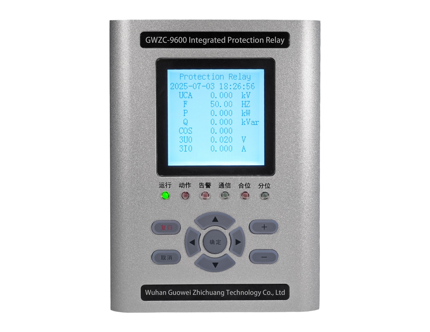
1. Introduction to Motor InverseTime Negative Sequence Overcurrent Protection
Motor inversetime negative sequence overcurrent protection is a protective mechanism designed for motor asymmetrical operation faults. When phasetophase short circuits, phase loss, voltage imbalance, or reversephase sequence startup occur in a motor, negative sequence current (I₂) is generated, which can cause rotor overheating or even burnout. This protection detects negative sequence current (I₂) and incorporates an inversetime characteristic (faster tripping for higher currents) to quickly isolate severe faults while allowing minor abnormalities to persist briefly. Its core algorithm is based on the I₂²t heating model, ensuring protection coordination with the motor’s thermal withstand capability. It is widely used in highvoltage motors and critical load motors.
2. Function of Motor InverseTime Negative Sequence Overcurrent Protection
The primary role of this protection is to prevent motor damage caused by asymmetrical faults. Negative sequence current induces doublefrequency eddy currents in the rotor, leading to localized overheating, which may cause insulation aging, bearing damage, or even winding burnout over time. The inversetime characteristic enables rapid tripping for severe faults (e.g., twophase short circuits) while issuing delayed alarms for minor imbalances (e.g., 5% voltage deviation) to avoid false trips. Additionally, it identifies abnormal conditions such as reversephase sequence startup and phase loss operation, compensating for the insufficient sensitivity of traditional overcurrent protection in handling asymmetrical faults, thereby enhancing motor operational safety.
3. Features of Motor InverseTime Negative Sequence Overcurrent Protection
This protection offers three core functions:
Realtime detection of negative sequence current (I₂) using symmetrical component analysis or dedicated algorithms.
Dynamic adjustment of tripping time based on preset inversetime curves (e.g., IEC standards or custom curves).
Coordination with positivesequence overcurrent and differential protection to form a comprehensive motor protection system.
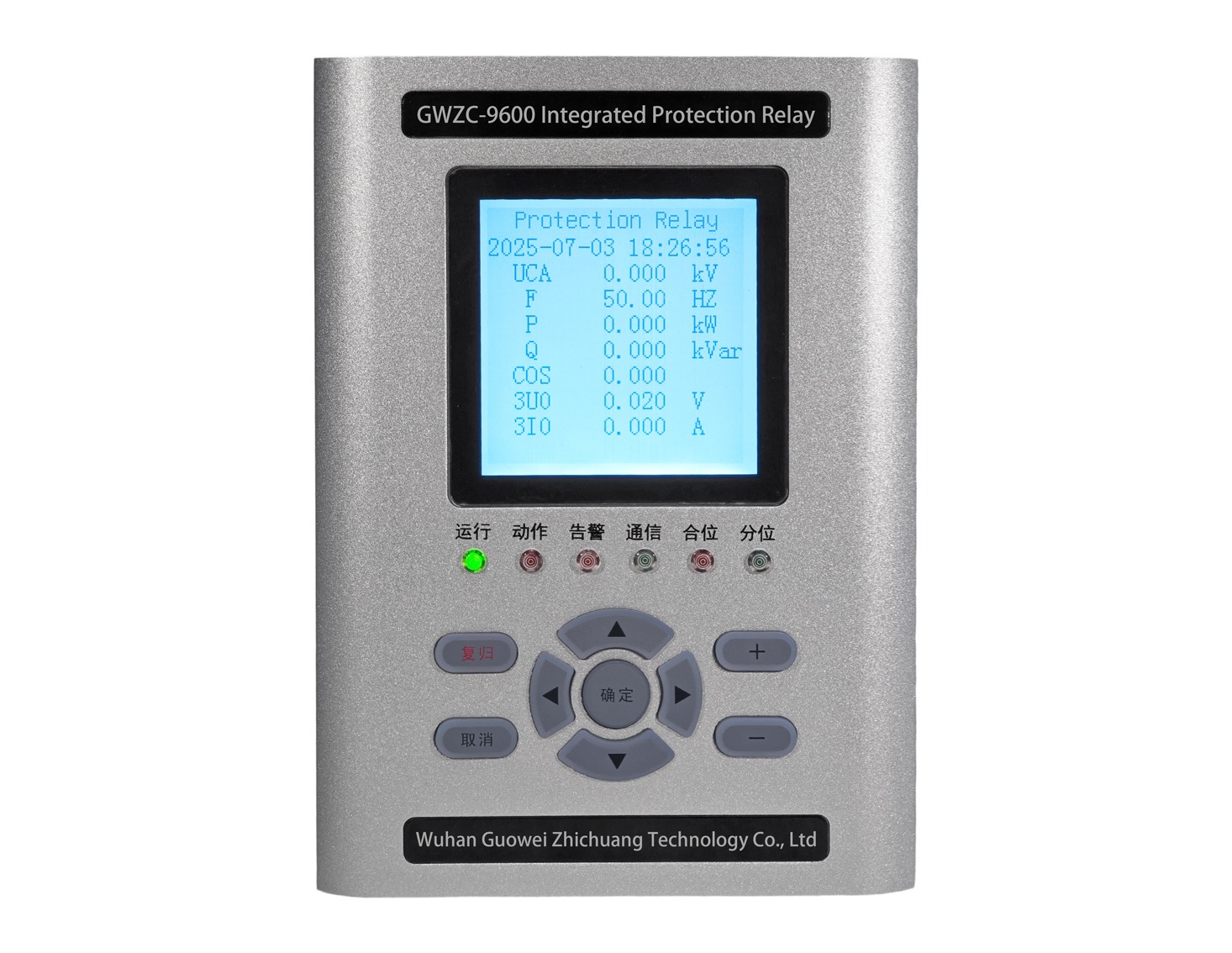
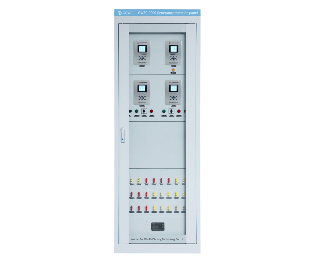
Advanced protection devices may also support negative sequence current waveform recording, fault location, and communication reporting for fault analysis. This protection can be integrated into microprocessorbased multifunction relays or standalone relays, meeting intelligent protection needs for various AC motors.
4. Principle of Motor InverseTime Negative Sequence Overcurrent Protection
Negative Sequence Current Generation:
When asymmetrical faults occur (e.g., twophase short circuits, reversephase sequence startup, or voltage imbalance), negative sequence current is generated in the stator windings. This current induces doublefrequency eddy currents in the rotor, causing localized overheating and endangering motor safety.
InverseTime Characteristic:
Tripping time is inversely proportional to fault current magnitude—higher I₂ results in faster protection response. The formula is typically:
t = K/{(I₂ / I2,set)α – 1}
Where:
t : Tripping time
K, α : Inversetime constants (to be set)
I2,set: Negative sequence current pickup threshold
5. Key Configuration Points for Motor InverseTime Negative Sequence Overcurrent Protection
Pickup Setting (I₂,ₛₑₜ): Typically 20%~40% of motor rated current (I_N), avoiding normal operational imbalance (e.g., inherent power supply asymmetry).
InverseTime Curve Selection:
Standard inversetime (IEC): α=1
Extreme inversetime (e.g., α=2): Faster response to severe faults.
Time Constant (K): Must match motor thermal withstand capability, usually based on manufacturerprovided negative sequence heating curves (I₂²t limits).
6. Typical Applications of Motor InverseTime Negative Sequence Overcurrent Protection
Phasetophase short circuits: Significant increase in I₂ triggers fast tripping.
Phase loss operation: I₂ ≈ 0.5I_N, leading to delayed tripping.
Voltage imbalance: Grid voltage asymmetry >5% may activate protection.
Reversephase sequence startup: High I₂ triggers instantaneous tripping.
7. Coordination with Other Protections
Positivesequence overcurrent protection: Handles symmetrical overloads.
Differential protection: Addresses internal short circuits; negative sequence protection supplements external asymmetrical faults.
Thermal overload protection: Negative sequence current heating can be integrated into thermal models.
8. Field Testing Considerations
Testing method: Inject negative sequence current using a protection tester (e.g., twophase current input with 120° phase shift).
Verification points:
Pickup threshold: Gradually increase I₂ until protection activates.
Time characteristic: Validate tripping times against the curve for different I₂ values.
Inrush avoidance: Brief I₂ during motor startup may require delay or blocking logic to prevent false trips.
