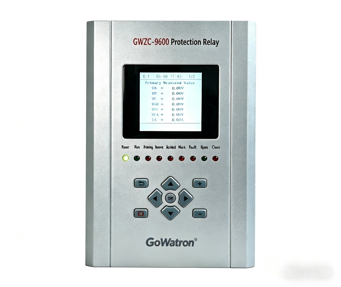
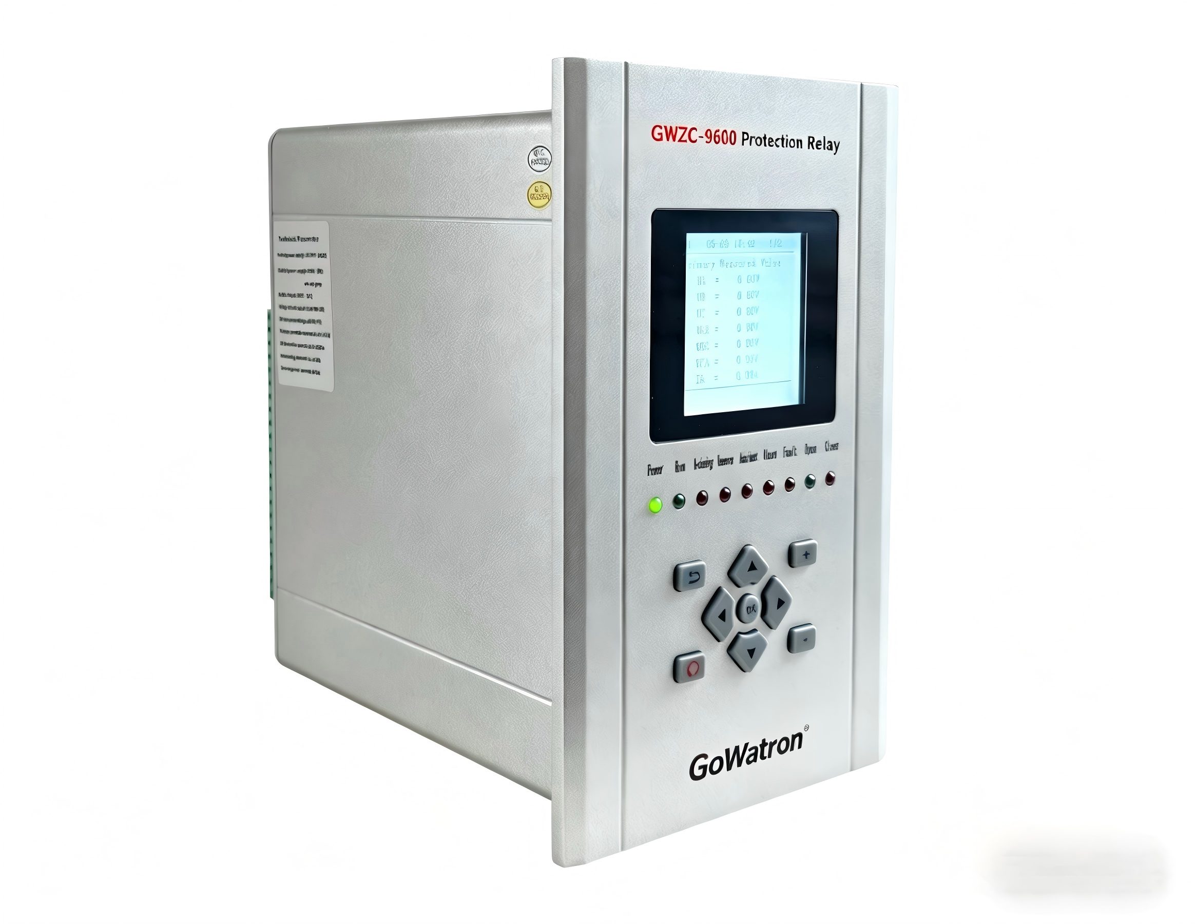
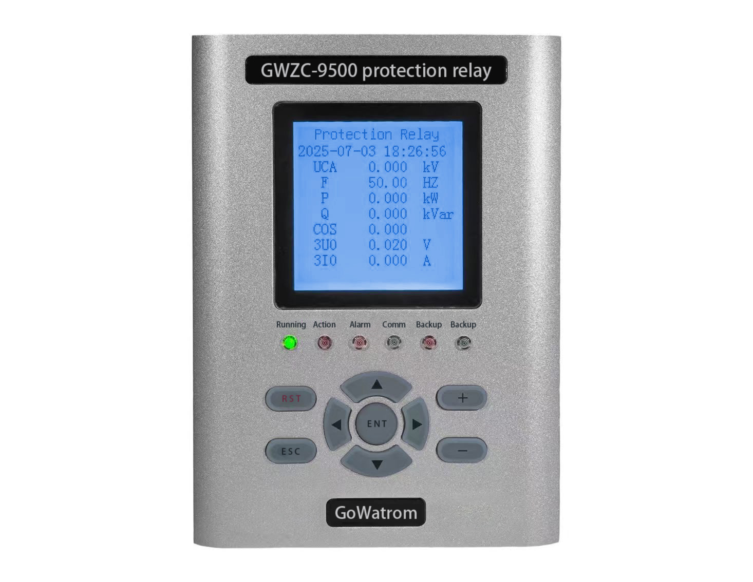
Our company produces a wide range of motor protection relays with various functions, including motor comprehensive protection relays and motor differential protection relays. We provide comprehensive support and welcome inquiries and purchases!
Motor differential protection serves as the primary protection for internal short-circuit faults in medium-to-high capacity motors (typically above 2000 kW or 6 kV). Its operating principle is based on Kirchhoff’s Current Law.
I. Motor Differential Protection/Working Principle
Motor differential protection operates by comparing the vector sum of the currents entering and leaving the motor winding.
1.Protected Zone: It provides precise protection for phase-to-phase and turn-to-turn faults (depending on sensitivity) occurring within the motor windings and its associated connecting leads. The protected zone is defined by the Current Transformers (CTs) installed at both the line side (source end) and the neutral side (load end) of the motor.
2.Fundamental Principle:
①A set of CTs with identical characteristics and ratios are installed at both the supply side (source end, e.g., switchgear) and the neutral side (load end) of the motor.
②The secondary windings of these two CT sets are connected in a circulating current scheme: the secondary winding of the source-end CT is connected in series opposition with the secondary winding of the load-end CT. The differential relay is connected in parallel across this loop.
③Under Normal Operation, Starting, or External Faults: The current flowing through the motor, under ideal conditions, results in currents I1 and I2 from the source-end and load-end CTs being equal in magnitude and opposite in phase. Consequently, the current flowing into the differential relay is their vector sum, i.e., the differential current Id = |I1 + I2| ≈ 0. Theoretically, the relay should not operate.
④During Internal Faults (within the protected zone): The fault point creates a shunt path for current. In this scenario, the current entering the motor I1 and the current leaving I2 are no longer equal. A significant differential current Id = |I1 + I2| ≈ I_fault (fault current) appears in the differential circuit. When this differential current exceeds the protection setting, the relay operates instantaneously, tripping the motor circuit breaker to isolate the power supply.
3.Key Technology: Overcoming Unbalanced Current
In practical applications, even under normal conditions, a small current known as unbalanced current I_unb exists in the differential circuit. This is due to CT transformation errors, differences in transient characteristics, and particularly the high intrush current (containing significant non-periodic components) during motor start-up. To prevent maloperation under these conditions, modern microprocessor-based differential protections typically employ the following method:
①Application of Restraint Characteristic: This is the core concept. The operation of the protection is determined not only by the differential current Id but also by a quantity called the restraint current Ir. Ir is typically calculated as (|I1| + |I2|)/2, representing the magnitude of the through-current.
②Operational Criterion: The relay’s operation is based on a percentage restraint characteristic curve. This curve defines the minimum value of differential current Id required for operation at different levels of restraint current Ir.
II. Motor Differential Protection/Purpose
1.Primary Protection: Acts as the fast and selective primary protection for phase-to-phase faults and severe turn-to-turn faults within the motor stator windings and its connecting leads.
2.Fast Fault Clearing: Operates very quickly (typically 20-60 ms), minimizing damage to the motor itself (e.g., preventing winding burn-out or core damage).
3.Enhances System Stability: Rapidly isolates the faulty motor, preventing fault escalation that could affect the plant power system or the stability of other operating equipment.
4.High Sensitivity: Compared to overcurrent protection, differential protection offers higher sensitivity for internal motor faults, especially for faults near the neutral point.
III. Motor Differential Protection/Setting Calculation
The core of setting calculation involves determining key parameters of the percentage restraint characteristic curve. The following calculations adhere to general industry principles; final values must be determined based on motor parameters, CT parameters, and the specific relay manufacturer’s instructions.
Prerequisites:
Ie: Motor rated current (secondary value, i.e., Ie = (Motor Rated Current) / CT Ratio)
CT Ratio: Current Transformer ratio
Is: Motor starting current (secondary value, typically 5 ~ 8 * Ie)
1. Minimum Pickup Current Iop0 (or Base Differential Setting)
①Purpose: To remain secure against the maximum unbalanced current present during normal motor operation at full load, caused by CT errors and measurement inaccuracies.
②Setting Calculation:
Iop0 = (0.2 ~ 0.4) * Ie
0.3 * Ie is often recommended as an initial value. Use the lower end for high-performance CTs and favorable conditions; use the higher end otherwise.
2. Restraint Characteristic Slope S (in per unit)
①Purpose: To remain secure against significant unbalanced currents generated during motor starting or external faults, conditions where CTs may experience saturation and the through-current Ir is high.
②Setting Calculation:
S = (0.3 ~ 0.6) or expressed as (30% ~ 60%)
A value of 50% (i.e., S = 0.5) is typically recommended.
Operational Equation: Id > Iop0 + S * (Ir – Ie) (when Ir > Ie, the relay operates in the slope restraint region).
Some relays use multi-slope characteristics, but the single-slope model is the most fundamental and common.
3. Breakpoint Current Ig (or Knee-Point Current)
①Purpose: Defines the point on the restraint characteristic curve where the transition occurs from the minimum pickup (unrestrained) region to the slope (restrained) operating region.
②Setting Calculation:
Ig = (0.5 ~ 1.0) * Ie
It is commonly set to 1.0 * Ie, meaning restraint becomes significant once the load current exceeds the rated current.
4. Instantaneous Differential Element Iop.inst (High Set)
①Purpose: To provide ultra-high-speed tripping for severe internal faults, bypassing the restraint characteristic. This ensures rapid clearance for heavy faults, even if CT saturation occurs.
②Setting Calculation:
Iop.inst = (8 ~ 12) * Ie OR set above the maximum possible differential current during motor starting.
③A value of 10 * Ie is often suggested. This setting must exceed the maximum expected unbalanced differential current during motor start-up.
5. Sensitivity Verification
①After determining the settings, it is necessary to verify that the differential protection has sufficient sensitivity for a two-phase metallic fault at the motor terminals (the farthest point within the protected zone).
②Verification Formula: Ksen = Id.min / Iop ≥ 2.0
Id.min: The differential current (secondary value) flowing into the relay for a two-phase metallic fault at the motor terminals under the minimum system short-circuit capacity.
Iop: The operating current value corresponding to the restraint current Ir for that fault condition, calculated from the restraint characteristic curve.
Summary
Motor differential protection is a high-performance protection scheme based on the principle of current vector difference. Its core function relies on the percentage restraint characteristic to discriminate between internal fault currents and normal unbalanced currents. The key to setting calculation lies in the appropriate selection of the minimum pickup current Iop0, the restraint curve slope S, and the breakpoint current Ig. This ensures security against maloperation during motor starting and external faults, while maintaining sensitivity and speed for internal faults.
Note: The above provides general setting principles. For practical engineering applications, it is imperative to strictly follow the setting guidelines and requirements specified in the technical manual for the specific protection relay being used, as algorithms and setting definitions can vary between manufacturers.