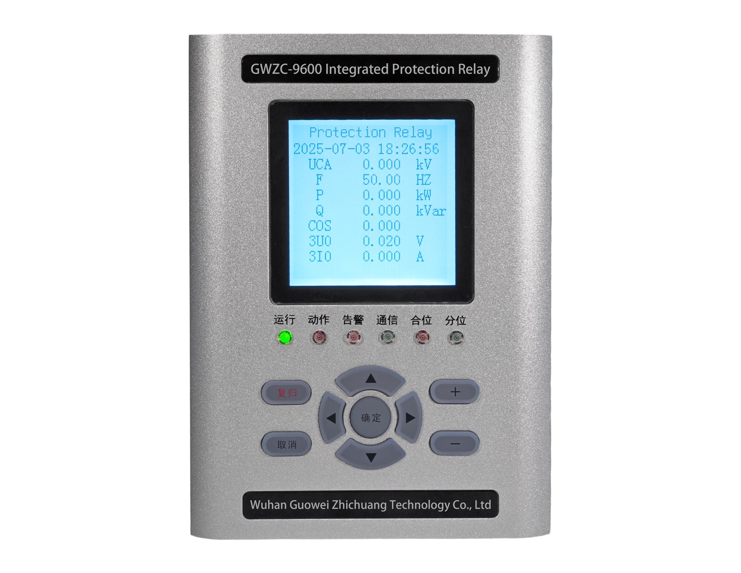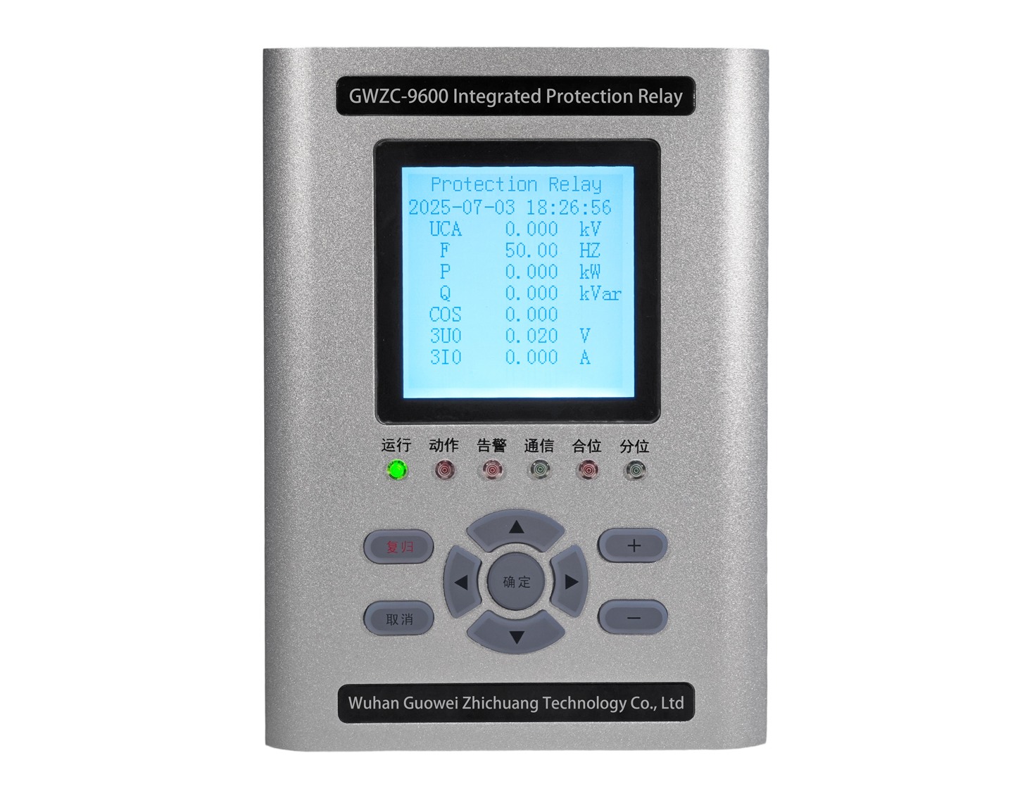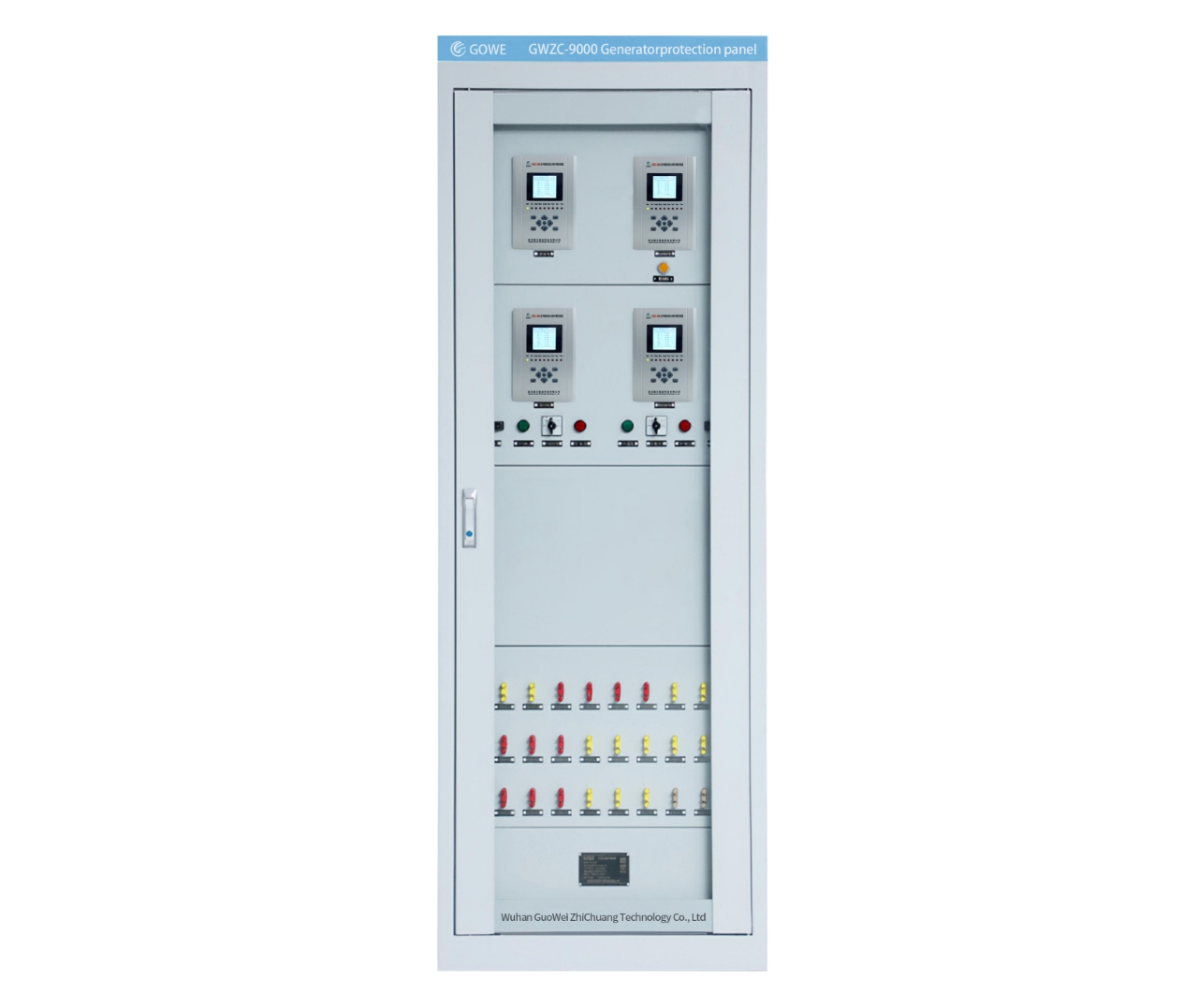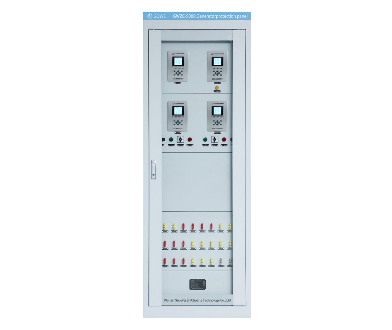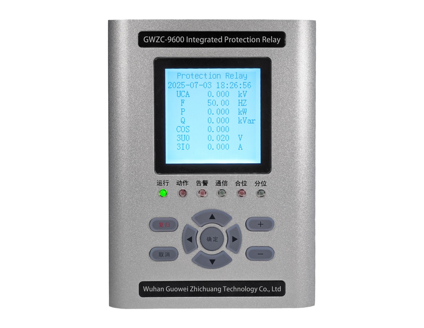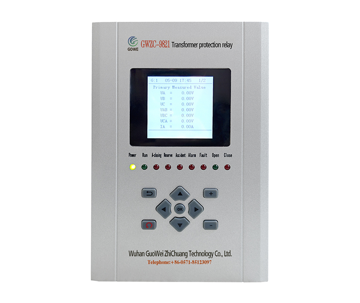
marine generator protection must include at least the following core protection functions. Additional functions may be required depending on system configuration (e.g., generator capacity, parallel operation, neutral grounding method):
1.Overcurrent Protection (50/51):
Instantaneous Overcurrent (50): Clears severe phase-to-phase short-circuit faults with extremely fast operation (millisecond level).
Definite Time / Inverse Time Overcurrent (51): Clears remote or moderate overloads and short-circuit faults, providing backup protection. Must coordinate with downstream protection (e.g., feeder breakers) to ensure selectivity. Inverse time characteristics better match equipment thermal withstand capability.
Short-Circuit Backup Protection: Typically provided by overcurrent protection (51), acting as backup to primary protection (e.g., differential).
2.Undervoltage Protection (27):
Detects abnormally low generator voltage (e.g., due to loss of excitation, main breaker mal-tripping, severe overload causing voltage collapse).
Usually incorporates a short time delay to ride through transient voltage sags caused by events like motor starting.
Acts to trip the generator or start standby units (depending on design).
3.Overvoltage Protection (59):
Detects abnormally high generator voltage (e.g., due to governor failure, excitation system failure).
Protects generator insulation and connected electrical equipment.
4.Reverse Power Protection (32):
Critically important! Prevents the prime mover (diesel engine, steam turbine) from being motored and driven in reverse if the generator acts as a motor. This avoids severe prime mover damage (e.g., diesel engine “runaway”).
Requires high sensitivity (typically capable of detecting reverse power levels between 2% and 15% of rated power).
Must incorporate sufficient time delay (typically 5-10 seconds) to ride through brief power oscillations and transfers during synchronizing/paralleling operations.
5.Overfrequency Protection (81O) & Underfrequency Protection (81U):
Detects abnormal grid frequency (usually caused by prime mover governor failure or severe system power imbalance).
Protects the generator and connected electrical equipment (especially motors).
6.Stator Earth (Ground) Fault Protection (64G / 51N/51G):
High-Resistance Grounded Systems (Most Common): Typically employs ground fault protection based on residual (zero-sequence) voltage (3U0) principle (64G). Offers high sensitivity (capable of detecting 5%-20% of rated voltage as 3U0). Usually operates with a delay for alarm or trip (depending on design).
Low-Resistance Grounded Systems: Can utilize residual (zero-sequence) current (3I0) based overcurrent protection (51N/51G).
This protection is vital for generator and system safety, preventing faults from escalating into phase-to-phase faults or damaging the core.
7.Loss of Excitation Protection (40):
Detects loss of generator field current or voltage, causing the generator to fall out of synchronism and absorb excessive reactive power from the system. This can lead to system voltage collapse and generator overheating. Acts to trip the generator.
Additional / Optional Protection Functions (Depending on system criticality, complexity, and Classification Society requirements):
8.Differential Protection (87G):
Primary protection. Detects phase-to-phase short-circuit faults within the generator stator windings, offering extremely high selectivity and speed (millisecond level). Typically applied to large-capacity generators (e.g., >1MW) or critical units.
Requires well-matched Current Transformer (CT) characteristics.
9.Rotor Earth (Ground) Fault Protection (64F):
Detects insulation failure to ground in the generator field winding (rotor). A single ground fault usually initiates an alarm (permitting limited operation), while a second ground fault causes severe vibration and necessitates immediate tripping.
10.Stator Thermal Overload Protection (49):
Models the heating process of the generator stator windings, providing inverse time characteristic overload protection. This more accurately reflects the actual thermal withstand capability of the equipment compared to definite time overcurrent protection.
12.Out-of-Step Protection / Pole Slipping Protection (78):
Detects loss of synchronism between the generator and the grid (or other paralleled generators). This condition can lead to equipment damage and system collapse. Typically applied to large generators or in complex power systems.
Overexcitation Protection (V/Hz Protection – 24):
Detects excessive Volts per Hertz (V/Hz) ratio. Prevents overheating of the generator and transformer cores due to magnetic flux density saturation.
