Instantaneous Overcurrent Protection (IOCP) is a protection scheme used in power systems to rapidly clear short-circuit faults. Its defining feature is zero intentional time delay (or minimal delay), with typical operating times of 20–50 ms, complying with IEC 60255-151 (Overcurrent Protection Standards) and IEEE C37.91 (Guide for Protection Relay Applications).
1. Instantaneous Overcurrent Protection Working Principle
IOCP operates based on current magnitude detection, triggering immediately when the fault current exceeds a preset threshold. The logic is as follows:
1)Current Sampling
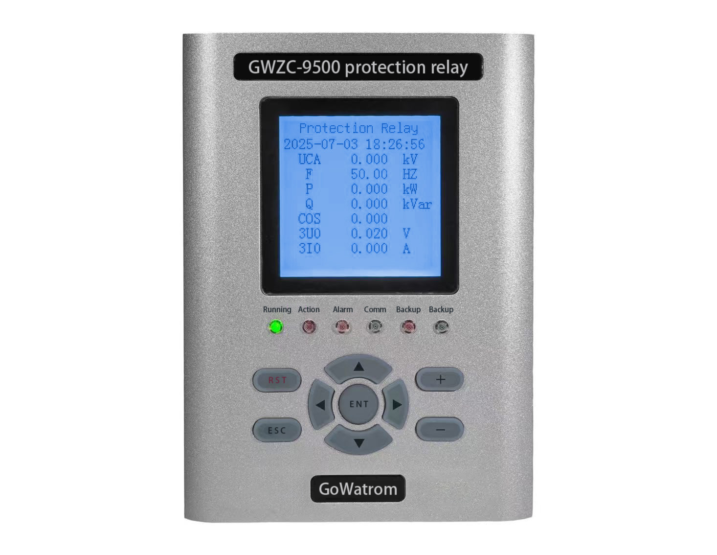
Current transformers (CTs) continuously monitor line current (secondary current typically 1A or 5A).
Protective relays (e.g., digital relays) sample and filter the current signal to eliminate harmonics and transients (per IEC 60255-6).
2)Current Comparison
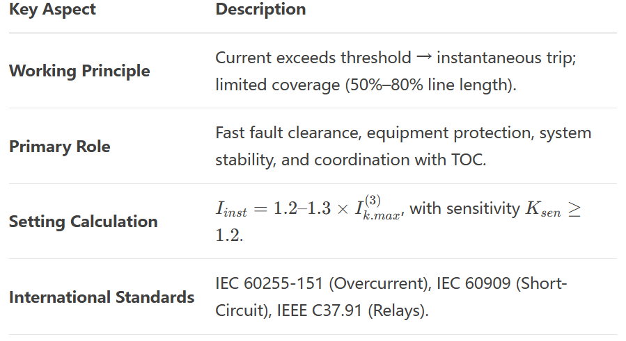
The measured current is compared against the instantaneous pickup setting (Iinst), typically set at 1.2–1.3 times the maximum short-circuit current at the line end.If Ifault≥IinstI the protection triggers without delay.
3)Trip Output
The relay sends a trip signal to the circuit breaker (per IEC 62271), isolating the fault.
Key Characteristics:
No intentional time delay (only inherent relay operating time, e.g., ~30 ms for electromechanical relays, ~10 ms for digital relays).
Limited protection coverage (typically 50%–80% of the line length from the relay location).
2. Instantaneous Overcurrent Protection Functions
The primary purpose of IOCP is rapid clearance of severe short-circuit faults, with specific roles including:
Preventing Equipment Damage
Short-circuit currents can cause thermal or mechanical stress to cables, transformers, and breakers. IOCP minimizes damage by fast fault clearance (refer to IEC 60909 for short-circuit calculations).
Maintaining System Stability
In high-voltage systems, faults may lead to voltage collapse or generator loss of synchronism. IOCP reduces fault duration, enhancing stability (per IEEE C37.102 for synchronous machine protection).
Selective Coordination
Works with time-delayed overcurrent (TOC) and overcurrent (OC) protection to form a graded protection scheme (e.g., three-step protection per IEC 60255-151).
Typical Applications:
Phase-to-phase fault protection in distribution lines (11kV–35kV).
Backup protection for motors and transformers.
Fast fault isolation in power plant auxiliary systems.
3. Instantaneous Overcurrent Protection Setting Calculation (Per International Standards)
IOCP settings depend on maximum short-circuit current and protection coverage, following IEC 60909 (short-circuit current calculation) and IEC 60255-151 (overcurrent protection settings).
(1) Instantaneous Pickup Setting (Iinst)
Iinst=Krel×I(3)k.max
Krel: Reliability factor (typically 1.2–1.3, accounting for CT errors, transients, and calculation tolerances).
I(3)k.max: Three-phase short-circuit current at the line end (under maximum system conditions).
Example:
For a 10kV line with Ik.max=4kA:
Iinst=1.3×4kA=5.2kA
The relay trips instantaneously if Ifault≥5.2kAI
(2) Sensitivity Verification (Per IEC 60255-151)
Verify whether the minimum fault current (e.g., two-phase fault) at the protection boundary can reliably trigger the relay:
Ksen=I(2)k.min/Iinst≥1.2
I(2)k.min : Two-phase short-circuit current under minimum system conditions.
If Ksen<1.2, adjust Iinst or supplement with time-delayed overcurrent protection.
(3) Special Considerations (Per IEEE C37.91)
For transformer-connected lines, avoid nuisance tripping due to inrush current (typically set at 8–12 times transformer rated current).
In distributed generation (DG) systems, consider directional overcurrent protection for fault current directionality.
Summary
Instantaneous Overcurrent Protection (IOCP) is the fastest short-circuit protection scheme in power systems, but its limited reach necessitates coordination with other protections (e.g., TOC, OC) for complete system security.