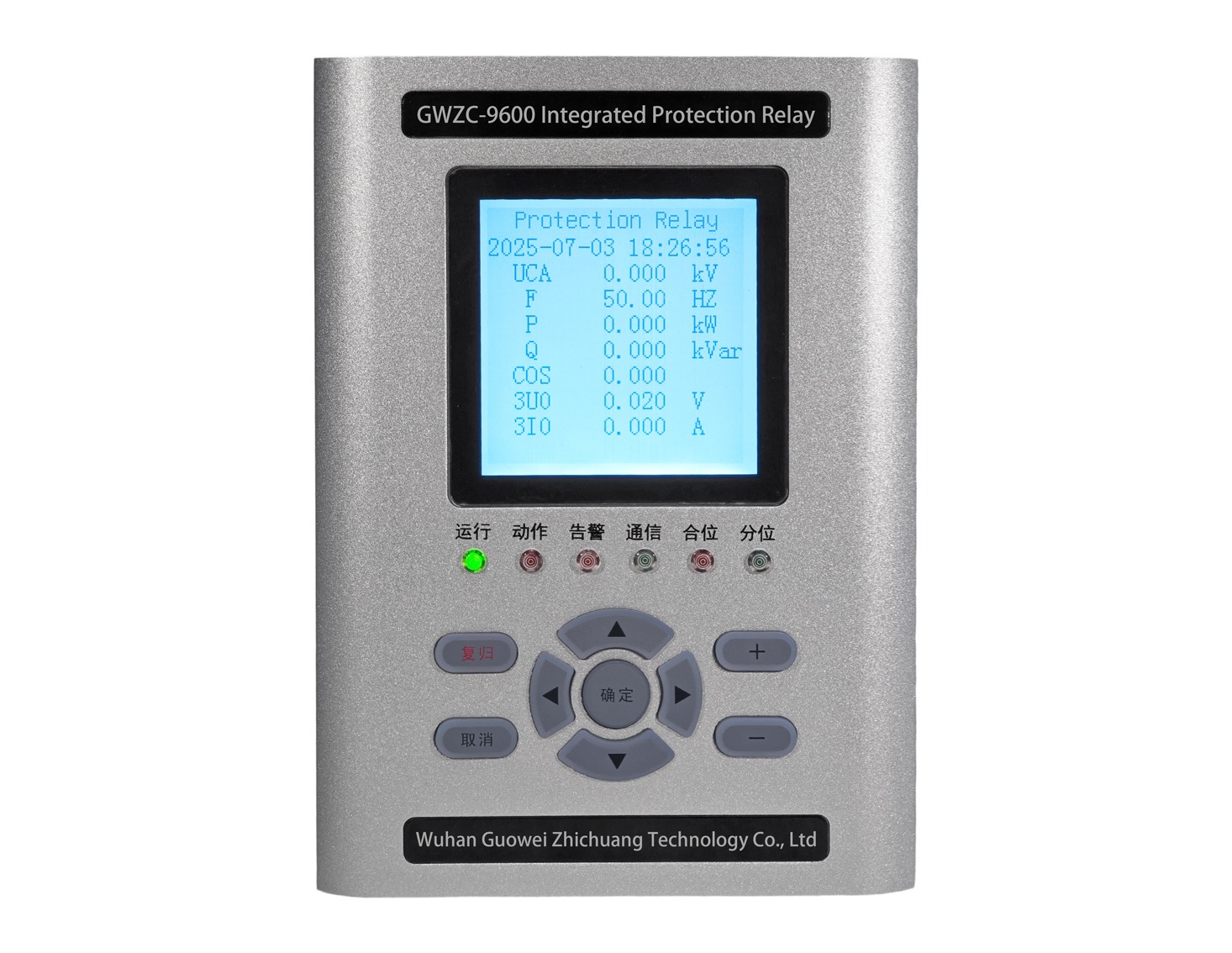
1. generator Underfrequency protection/Working Principle
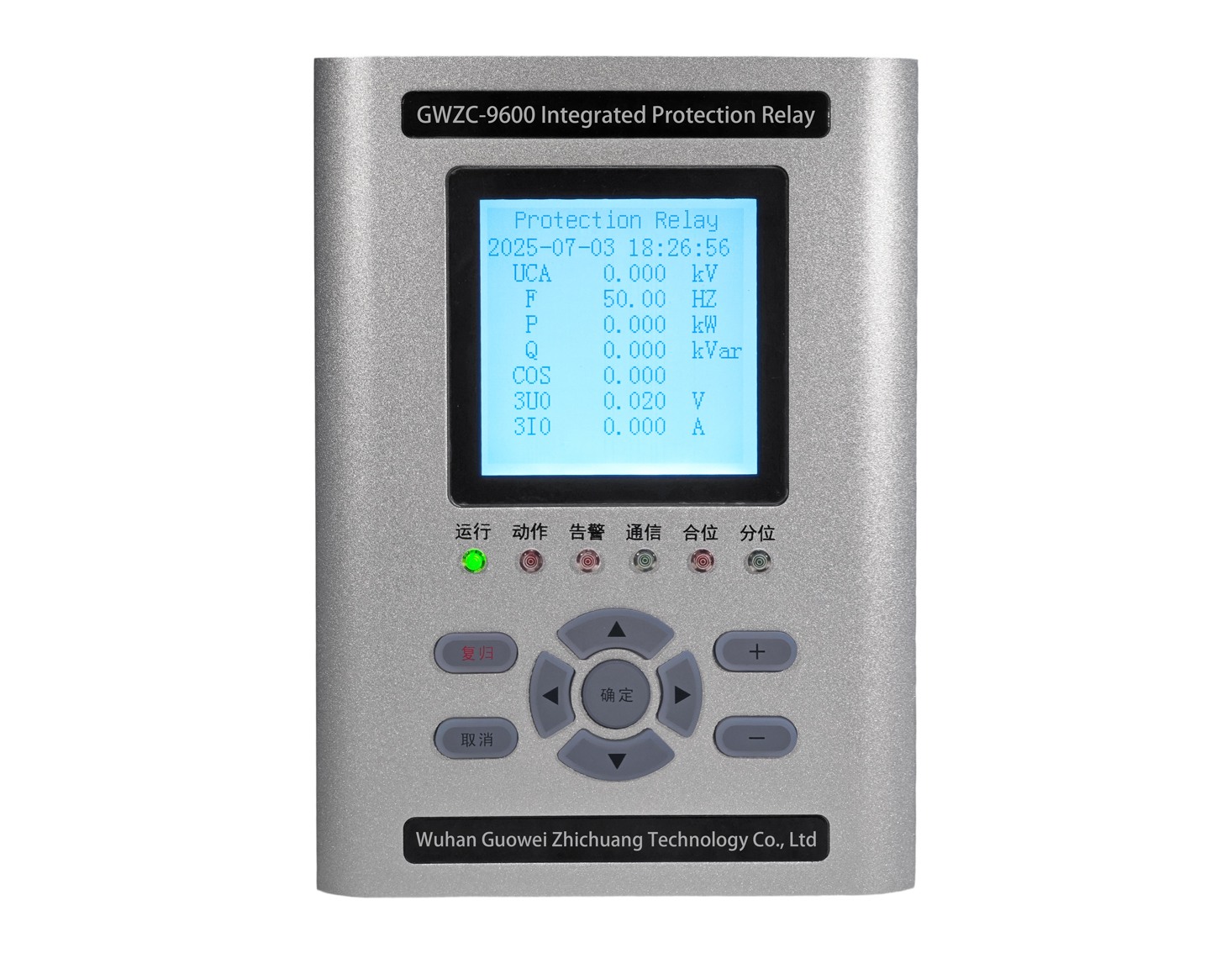
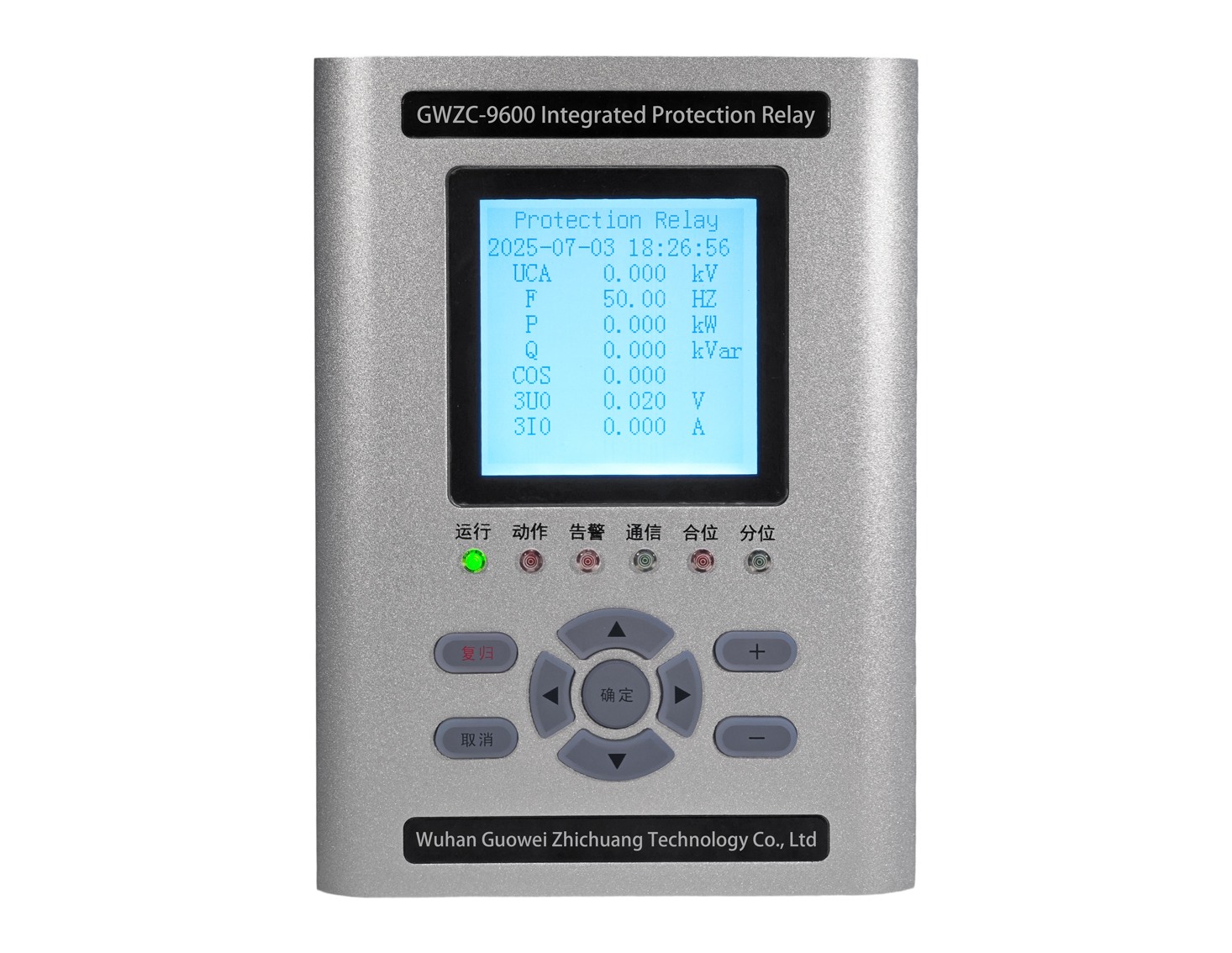
Generator Underfrequency Protection, internationally standardized under ANSI/IEEE C37.2 as code 81, operates on a core principle of continuously monitoring the AC voltage frequency at the generator terminals or at the station auxiliary bus.
The protection is activated when the monitored frequency falls below a predefined setpoint and remains there for a specific duration, triggering an alarm or a direct trip command.
Relationship between Frequency and Speed: For a synchronous generator, the output electrical frequency f is directly proportional to the rotor speed N and the number of pole pairs P (f = (P * N) / 120). Therefore, a decrease in system frequency directly indicates a decrease in the prime mover (turbine) speed, signifying that the mechanical input power is less than the electrical output power, putting the generator in a motoring condition.
Root Cause of Frequency Decline: This typically occurs due to a deficit of active power in the system (e.g., a sudden trip of a large generating unit while the load remains constant). All remaining online generators will compensate for this deficit by converting the kinetic energy stored in their rotors into electrical energy, resulting in a decrease of their rotational speed (and thus a drop in frequency).
Protection Timing Characteristics: Underfrequency protection typically employs an Inverse Time or Multiple Definite Time Stage characteristic.
Inverse Time: The lower the frequency, the greater the power deficit and the more critical the situation, leading to a shorter allowed time delay. This better aligns with the thermal accumulation damage model of the generator and turbine.
Multiple Definite Time Stages: Several different frequency thresholds are set, each with a fixed time delay. For example, 59.0 Hz with a 10-second delay, 58.5 Hz with a 2-second delay, etc. (for a 60Hz system).
2.generator Underfrequency protection/ Purpose
The generator underfrequency protection serves two primary critical functions:
①Preventing Turbine Blade Damage
This is the primary and most critical purpose. Turbine blades are designed such that their natural vibrational frequencies avoid mechanical resonance at rated speed and its harmonics. When system frequency decreases, the blades’ vibrational frequencies decrease proportionally, potentially moving into new resonance zones. Under resonant conditions, blades are subjected to immense cyclic stress. Prolonged operation or repeated exposure to these conditions can lead to metal fatigue, cracking, and ultimately blade failure, causing catastrophic damage.
Underfrequency protection prevents sustained operation of the turbine at harmful low frequencies (low speeds) by disconnecting the generator from the system in a timely manner.
②Contributing to System Frequency Stability and Implementing “Underfrequency Load Shedding”
Although the action of generator underfrequency protection is to trip (which reduces system generation further), in some designs, it acts as the last line of defense within the overall power system’s Underfrequency Load Shedding (UFLS) scheme.
When a severe active power deficit occurs, non-critical loads are shed first (via the UFLS scheme). If the load shed is insufficient or fails to halt the frequency decline, the frequency will continue to drop to levels that endanger the power plant itself. At this point, the generator underfrequency protection operates to prevent damage to the primary plant equipment and to isolate a “healthy” island from the system, thereby avoiding a complete system-wide frequency collapse.
3. generator Underfrequency protection/Setting Calculation
The objective of setting calculation is to prevent damage to the generator while coordinating with system-side frequency control measures (like UFLS) to avoid unnecessary tripping.
The settings primarily consist of two core parameters: the Frequency Setpoint (f_set) and the Time Delay (t_delay).
Calculation Steps and Considerations:
Step 1: Determine the Minimum Safe Frequency Limit
This data must be provided by the Turbine Manufacturer. This value varies for different capacities and types of turbines (e.g., nuclear, fossil-fueled, gas).
Typically, for modern large turbines, the minimum allowable frequency for continuous operation is around 57.0 Hz (for 60Hz systems) or 47.5 Hz (for 50Hz systems). The resonance zones to be avoided are also provided by the manufacturer in the form of a frequency versus cumulative time curve.
Step 2: Coordinate with the System Underfrequency Load Shedding (UFLS) Scheme
Obtain the UFLS scheme from the power system operator. This scheme specifies the delays for shedding load blocks at different frequency levels.
The generator underfrequency protection settings must be set to operate after the last stage of the UFLS scheme. In other words, the protection should only operate if the system has shed all possible load and the frequency continues to decline to a level that threatens the generator itself.
Coordination Principle: The trip frequency of the generator protection should be lower than the frequency setpoint of the last UFLS stage, or its time delay should be longer than that of the last UFLS stage.
Step 3: Determine the Protection Characteristic and Settings
Common Method: Based on the Turbine Life Consumption Curve
The turbine manufacturer usually provides a “frequency versus cumulative operating time” curve. This curve specifies the maximum cumulative time the turbine can operate at a specific frequency before reaching its life consumption limit.
Example (for a 50Hz system):
①Obtain Manufacturer’s Curve: Assume the manufacturer specifies:
Below 48.0 Hz, cumulative operating time must not exceed 10 minutes.
Below 47.5 Hz, cumulative operating time must not exceed 2 minutes.
Below 47.0 Hz, cumulative operating time must not exceed 30 seconds.
②Set Frequency Stages and Delays: Based on this data, multiple definite time stages or an inverse time curve can be set.
Option 1: Multiple Definite Time Stages
Stage 1: f_set1 = 48.0 Hz, t_delay1 = 600 seconds (10 minutes) – ANSI 81-1
Stage 2: f_set2 = 47.5 Hz, t_delay2 = 120 seconds (2 minutes) – ANSI 81-2
Stage 3: f_set3 = 47.0 Hz, t_delay3 = 30 seconds – ANSI 81-3
Option 2: Inverse Time Curve
Select an inverse time characteristic curve (e.g., per IEEE standard inverse-time formulas) that lies entirely below the manufacturer’s life consumption curve, maintaining a safety margin. This requires support from the protection relay and corresponding calculations.
Step 4: Consider Blocking Logic
To prevent maloperation when the generator is not synchronized to the grid (e.g., during start-up or shutdown), underfrequency protection must include blocking conditions. The most common blocking condition is:
Circuit Breaker Closed Status: The underfrequency protection is only enabled when the Generator Circuit Breaker (GCB) is closed. This can be implemented via circuit breaker auxiliary contacts or through the relay’s logic programming.
Under Voltage Blocking: If voltage is too low (e.g., below 70% of Un), frequency measurement may be unreliable, and the protection can be blocked. The priority of this blocking must be carefully considered.
Excitation System Status: Sometimes interlocked with the status of the field breaker.
Summary Setting Example:
Protection Function: Underfrequency Protection (ANSI 81)
Frequency Setpoint: 47.5 Hz (To be finalized based on manufacturer data and system coordination)
Time Delay: 15 seconds (To be finalized based on manufacturer data and system coordination, often using inverse time)
Blocking Condition: Automatically disabled when the Generator Circuit Breaker is open.
Action: Unit Trip (Trip GCB, de-excitation, close main steam stop valves / guide vanes).
Important Notes:
Accuracy: The numerical values provided above are for illustration only. Actual settings must be based on official data from the turbine manufacturer and the specific grid code requirements.
Coordination: Coordination with the system UFLS scheme is critical for ensuring power system security and stability, preventing the exacerbation of a system collapse due to premature generator tripping.
Dynamic Simulation: For large, critical generator units, the underfrequency protection settings may need to be validated and optimized through power system dynamic simulation studies.
