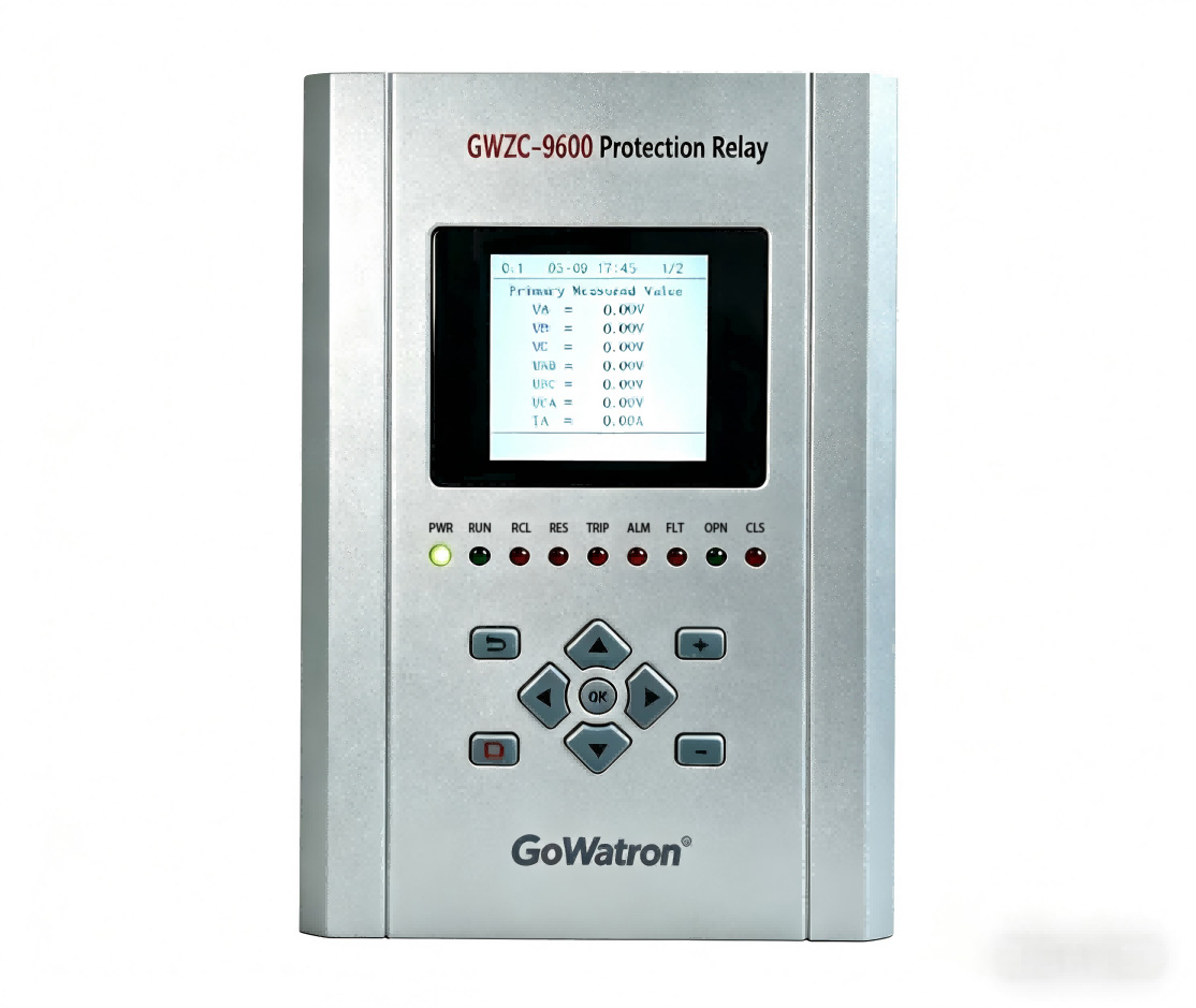
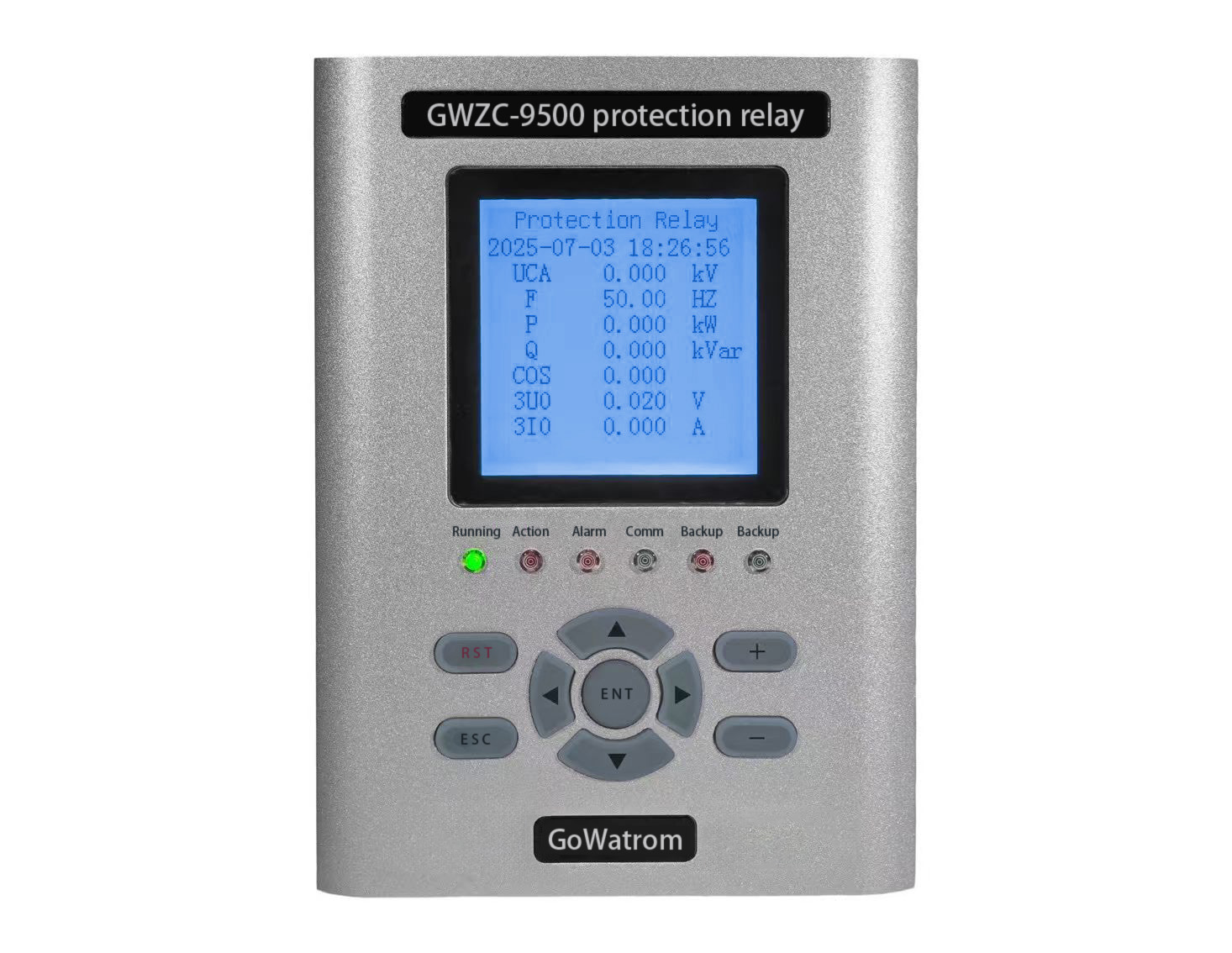
Our company’s GWZC-9681 Generator Backup Protection Relay and GWZC-9681C Generator Comprehensive Protection Relay both feature comprehensive reverse power protection functions for generators. We welcome inquiries and further information. Below, we provide a detailed introduction to the working principle, function, and setting calculation of generator reverse power protection.
1. generator reverse power protection /Working Principle
Reverse Power Protection is fundamentally a directional power protection used to detect the flow of active power.
Core Principle: It calculates the active power internally within the relay based on the measured voltage and current at the generator terminals (or outlet). The active power is calculated using the formula P = √3 × V × I × cosφ, where cosφ is the power factor.
Directional Discrimination:
Forward Power: When the generator delivers active power to the system (grid), the power direction is defined as positive. This is the normal operating state of the generator.
Reverse Power: When the system (grid) delivers active power to the generator, the power direction is defined as negative or “reverse”. This means the generator is not producing power but is operating as a motor, consuming active power from the system.
Protection Operation: When the relay detects that the active power direction is “reverse,” and its magnitude exceeds the set threshold for a duration longer than the set time delay, the protection device will issue a trip command to disconnect the generator from the grid.
In simple terms: Reverse power protection continuously monitors “who is driving whom.” If it detects that the grid is “motoring” or driving the generator, rather than the generator driving the turbine, it identifies this as an abnormal condition and takes action.
2. generator reverse power protection/Purpose
The primary functions of reverse power protection are as follows:
①Protection of the Prime Mover:
For Steam Turbines: Under reverse power conditions, the steam turbine operates as a motor. The blades, especially the long last-stage blades, rotate at high speed in a dense steam environment, creating a windage or blading friction effect. This can cause overheating and potential damage to the blades. This is one of the most critical consequences.
For Gas Turbines: Similarly, they can operate as a motor, potentially leading to overheating and damage in the compressor section.
For Hydro Turbines: Reverse power operation can cause the turbine to operate in a pump mode, leading to unstable water flow and mechanical vibrations, which can damage the runner and guide vanes.
②Protection of the Overall Unit: Prevents the generator from operating in an unintended “motor” mode, avoiding unnecessary stress on mechanical components such as the shaft and couplings.
③System Security: Promptly isolates the faulty generator from the grid, preventing it from absorbing significant active power from the network. This helps maintain grid stability and frequency, and avoids imposing an additional burden on other operating units within the power plant.
Note: For specific operating conditions, such as the “compensator mode” operation of a hydro turbine, where the generator needs to absorb a small amount of active power from the system to maintain rotation, the reverse power protection must be blocked, or a dedicated Programmed Reverse Power protection scheme should be used
3. generator reverse power protection/Setting Calculation
The setting calculation for reverse power protection involves two key parameters: the Power Setting and the Time Delay.
The power setting must be set at a level that reliably detects a reverse power condition while avoiding maloperation during normal system conditions (e.g., power swings, momentary reversal during synchronization).
Calculation Basis:
Reverse power is primarily consumed in overcoming the various mechanical and electrical losses of the generator set, including:
Bearing friction losses
Windage losses
Core iron losses
Copper losses
The sum of these losses represents the total unit losses. The power setting for reverse power protection should be set higher than the total losses of the unit when operating as a motor.
Calculation Formula: P_set = -K_rel × P_loss
Where:
P_set: The setting value for reverse power protection (in kW or MW, the negative sign indicates the reverse power direction).
P_loss: The total losses of the generator set (in kW or MW). This value is typically provided by the manufacturer or determined by tests (e.g., a coast-down test). It is usually in the range of 0.5% to 3% of the generator’s rated power.
K_rel: Reliability factor, typically 1.2 to 1.5. This ensures the protection operates reliably despite potential measurement and calculation errors.
Typical Setting Range:
Steam Turbine Generators: Typically set between -0.5% to -3% of the generator’s rated power (Pn).
Hydro Generators: Due to relatively higher losses, typically set between -0.5% to -1.0% of Pn.
Example: A 300 MW steam turbine generator has total losses of approximately 2.4 MW (0.8%). Using a reliability factor of 1.3:
P_set = -1.3 × (300 × 0.008) = -1.3 × 2.4 ≈ -3.12 MW
Therefore, the power setting could be set to -3 MW (approximately -1% of Pn)
b) Time Delay
The time delay is set to override temporary, non-fault power reversals.
Conditions to Consider:
①Synchronization: A brief power reversal or surge can occur at the moment the generator is synchronized to the grid due to phase angle differences.
②System Power Swings: During power system oscillations, the power direction can fluctuate momentarily.
③Turbine Control Valve Activity: Minor power fluctuations can occur during power regulation.
Typical Setting Range:
The time delay is typically set between 1 to 10 seconds.
For steam turbines, a typical value is 3 to 10 seconds, providing sufficient time to ride through the aforementioned transients while being fast enough to prevent thermal damage to the blades.
For hydro turbines, the delay can be slightly shorter, e.g., 1 to 5 seconds.
Setting Calculation Summary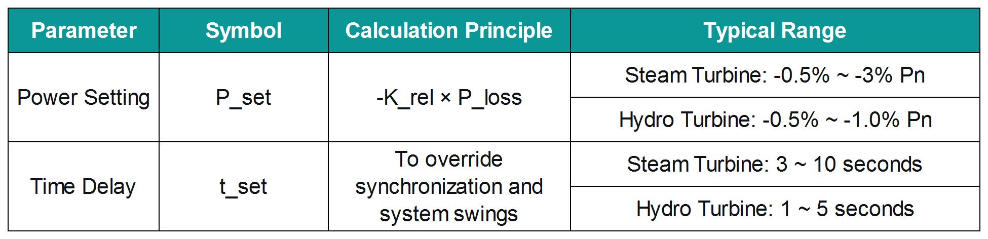
Important Considerations:
Final settings must be based on recommendations from the generator and prime mover manufacturers.
The influence of Current Transformer (CT) and Voltage Transformer (VT) ratios and phase angle errors on power measurement accuracy must be considered.
In practice, dynamic tests are often necessary to validate the correctness of the settings.