1. Generator 100% Stator Earth Fault Protection Principle
Traditional stator earth fault protection (e.g., fundamental zero-sequence voltage protection) covers only 80–95% of the stator winding, leaving a dead zone near the neutral point. 100% stator earth fault protection combines dual principles for full coverage:
(1) Third-Harmonic Voltage Principle (Neutral Zone Protection)
Mechanism: Under normal operation, magnetic field distortion in the air gap generates third-harmonic voltages (U3N at neutral, U3T at terminal). The ratio satisfies:
|U3N|/|U3T|≈1
Fault Response:
Earth fault near neutral: U3N decreases,increases → Ratio U3T drops significantly.
Protection Criterion:|U3N|/|U3T|<Kset(Typical setting: Kset=0.3−0.5).
(2) Low-Frequency Injection Principle (20 Hz Injection, Full Coverage)
Method: Injects a 20 Hz voltage signal via the neutral earthing transformer or dedicated coupler.
Fault Detection:
Normal: High impedance → Small injection current (Iinj).
Earth fault: Stator insulation resistance (Rf) drops → Iinj increases.
Criterion: Monitors Iinj or computes Rf:
Rf=Uinj/Iinj(Trip if Rf<Rset )
2.generator 100% stator earth fault protection Functions
Full Winding Coverage: Eliminates dead zone (5–20% near neutral), protecting 100% of the stator.
High Sensitivity : Detects high-resistance faults (up to several kΩ), preventing fault escalation.
Dual Redundancy : Third-harmonic + injection principles act as mutual backups.
Backup Protection : Provides backup for 95% stator earth fault protection.
3. generator 100% stator earth fault protection Setting Calculations
(1) Third-Harmonic Voltage Protection
Ratio Setting:
Kset=Krel×(|U3N|/|U3T|)min
Krel: Security margin (1.2–1.5).
(|U3N|/|U3T|)min: Minimum measured ratio under normal operation (typically 0.5–1.0).
Typical Setting: Kset =0.3−0.5.
(2) Low-Frequency Injection Protection
Insulation Resistance Setting:
Rset= Rins.min/Krel
Rins.min : Minimum allowable stator insulation resistance (usually 5–10 kΩ).
Krel: Security margin (1.5–2.0).
Typical Setting: Rset=1−5kΩ.
Time Delay: 0.5–1.0 s (avoids transient disturbances).
(3) Fundamental Zero-Sequence Voltage Protection (95% Coverage, Coordination)
Setting:
U0.set=Krel×U0.max
U 0.max: Maximum unbalanced voltage during normal operation (5–10 V secondary).
Krel: Security margin (1.3–1.5).
Typical Setting: U0.set=5−15V (secondary).
Engineering Considerations
1.Third-Harmonic Scheme Applicability: Performance varies with load/power factor; verify across all operating conditions.
2.Injection Scheme Advantage: Unaffected by operating state; requires dedicated injection equipment.
3.Setting Validation: Measure U3N/U3T ratio and fundamental U0 during commissioning.
4.Coordination: 100% protection delays (0.5–1 s) coordinate with instantaneous 95% protection.
Example Setting Procedure:
1.Measure:U3N/U3T at no-load/full-load; obtain minimum ratio 0.6.
2.Set third-harmonic protection: Kset=1.3×0.6=0.48→0.5.
3.Set injection protection: Rset=3kΩ (per manufacturer).
4.Set zero-sequence voltage:U0.set=1.3×8V=10.4V→10V
Generator 100% Stator Earth Fault Protection Summary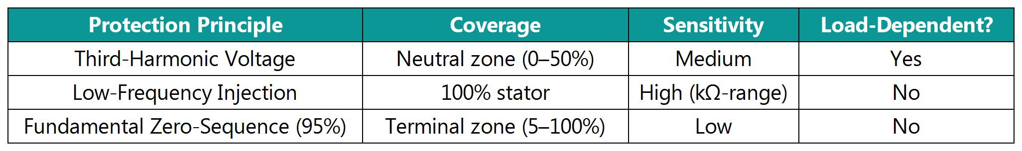
Conclusion: The synergy of third-harmonic monitoring and active low-frequency injection enables dead-zone-free, high-reliability stator earth fault protection, essential for large generators.
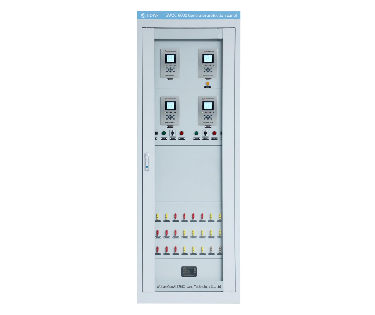
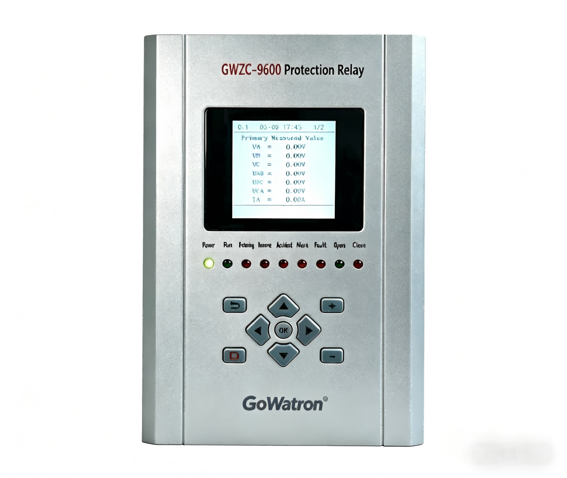
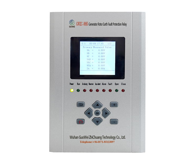
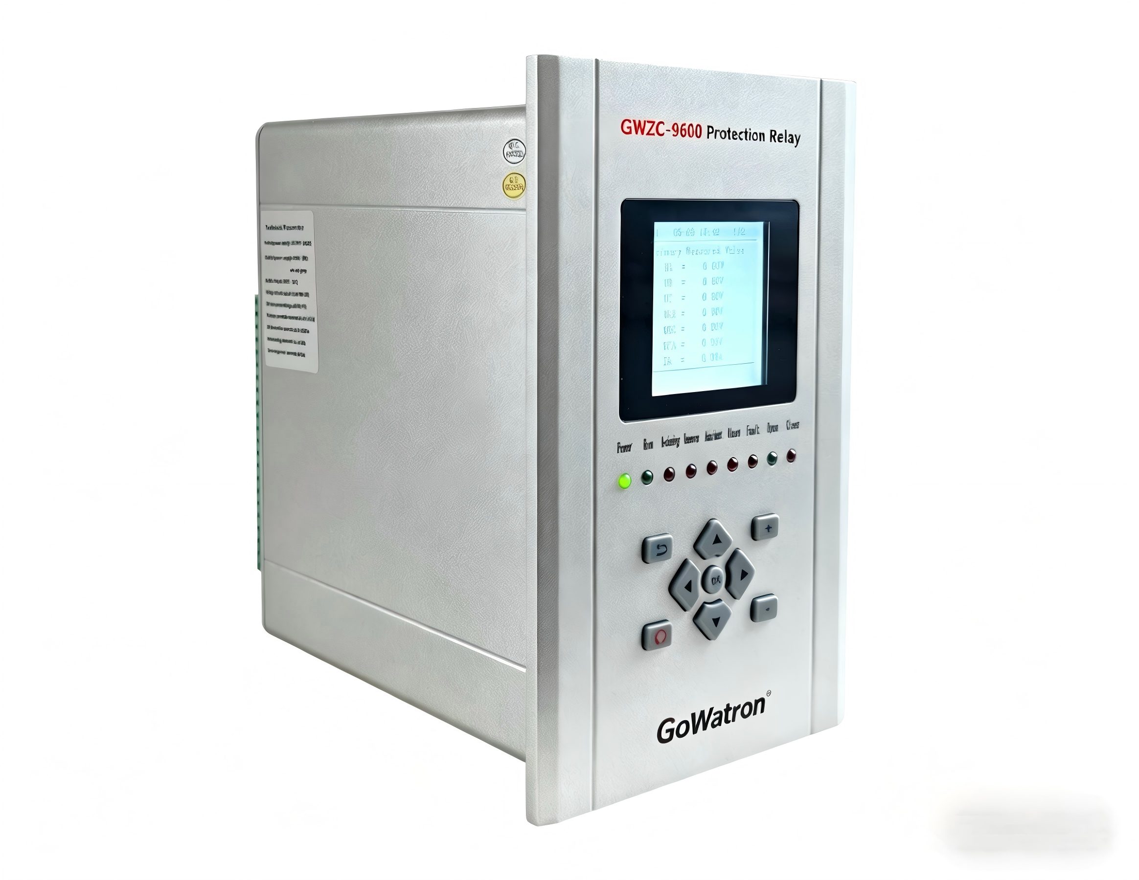
Our company’s GWZC-9886 Generator Backup Protection Relay features 100% Stator Ground Protection. Welcome inquiries and procurement!