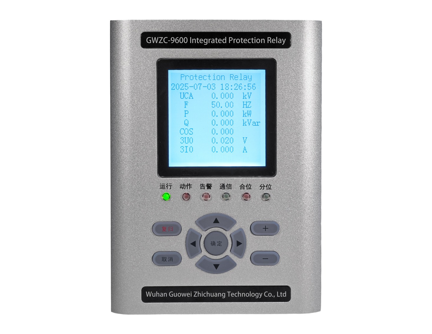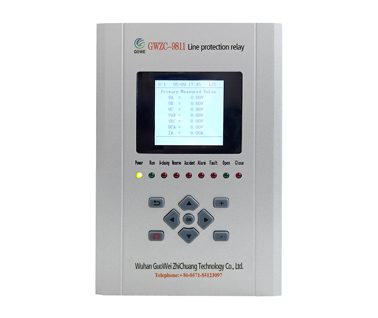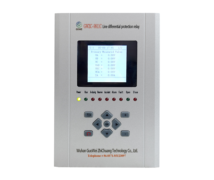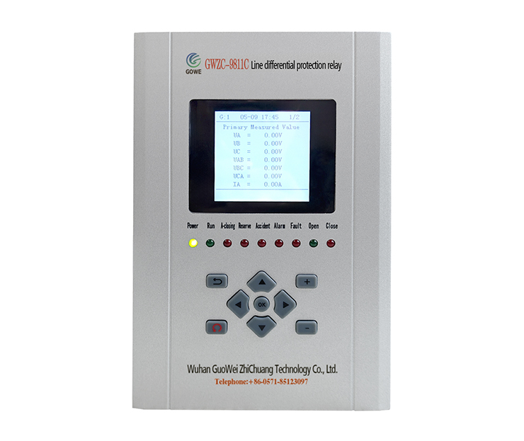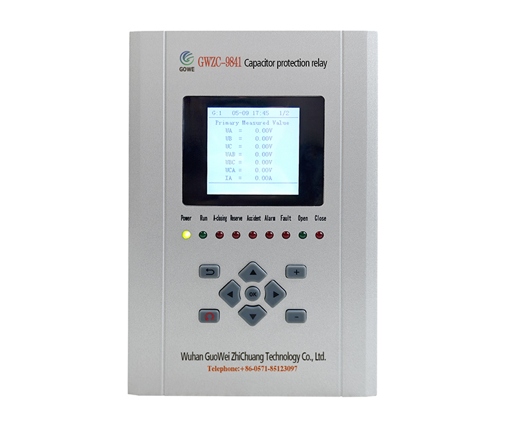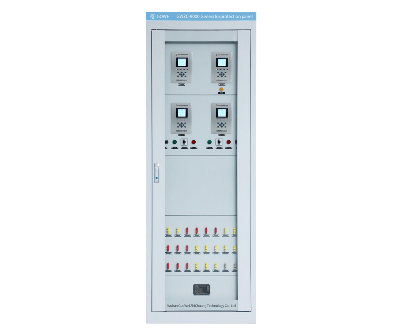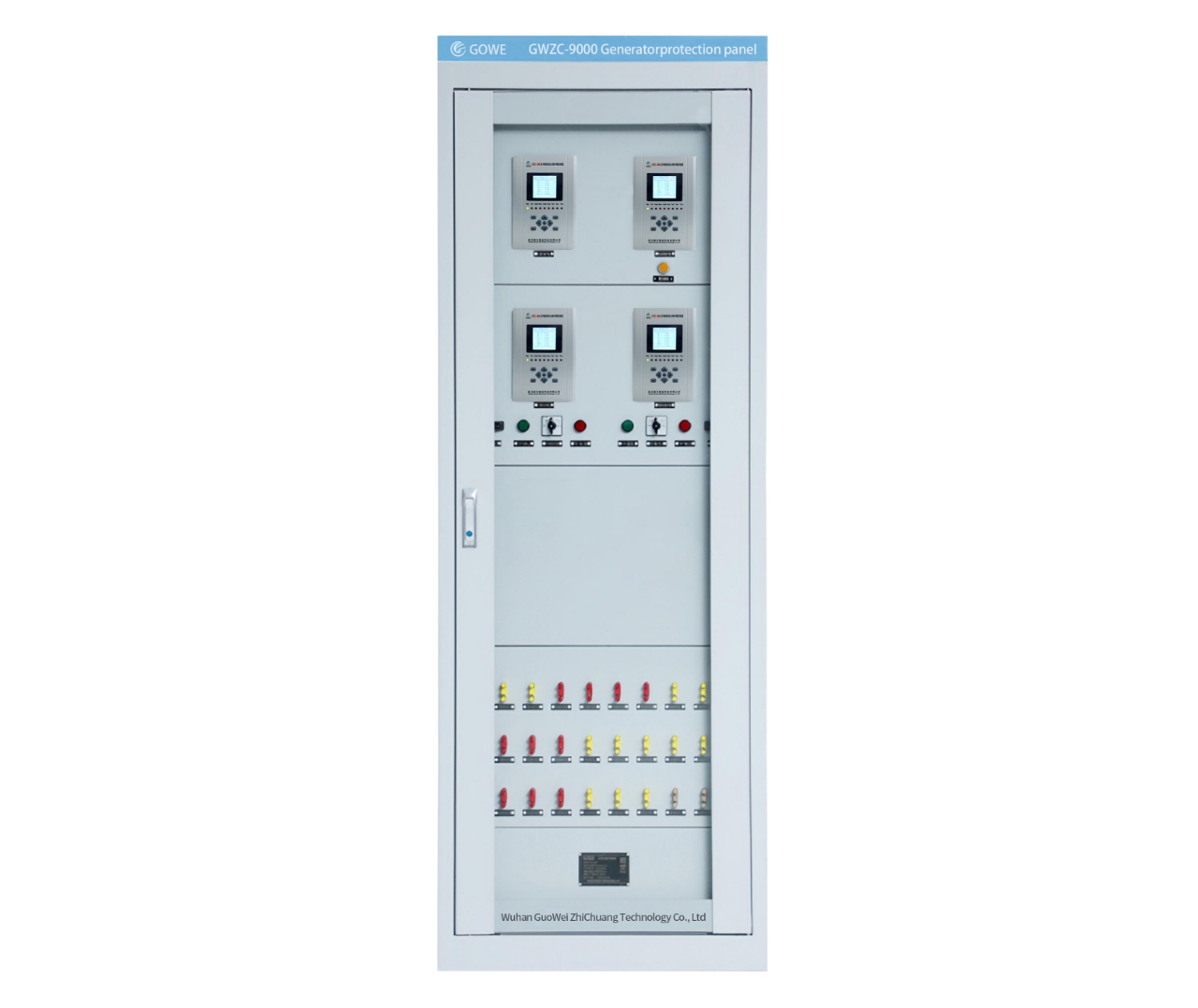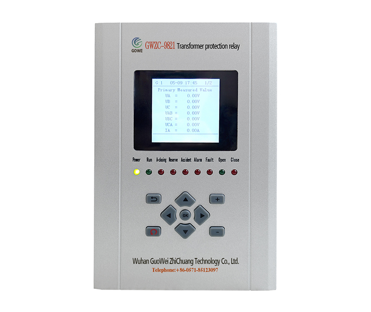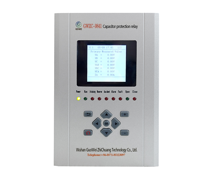
Feeder protection relays are a type of line protection relay and serve as critical devices in distribution systems for protecting power cables (feeders). They integrate multiple protection functions to achieve comprehensive, reliable, and selective protection. Below are the commonly used protection functions of feeder protection relays, along with their corresponding ANSI codes.
I. Core Overcurrent Protection Functions
This is the most fundamental and core part of feeder protection.
1.Instantaneous Overcurrent Protection
ANSI 50
Function: Initiates an immediate, time-delay free trip when the current exceeds a very high setpoint (typically used for detecting severe faults like phase-to-phase short circuits). It provides rapid fault clearance but requires coordination with upstream protection.
Application: Protection against severe faults close to the feeder origin.
2.Definite Time Overcurrent Protection
ANSI 51
Function: When the current exceeds a set value (typically lower than the 50 setting), the relay trips after a fixed, pre-defined time delay. This delay is used for time coordination with downstream (e.g., lateral circuits) and upstream (e.g., main transformer) protection.
Application: Serves as the primary protection for the feeder and backup protection for downstream elements.
3.Inverse Time Overcurrent Protection
ANSI 51V or 51
Function: The operating time is inversely proportional to the magnitude of the fault current. Higher fault currents result in shorter operating times. It provides better coordination with equipment damage curves and is often used for protecting motors, transformers, and also applied in feeders.
Types: Typically follows standard curves such as EI (Extremely Inverse), VI (Very Inverse), MI (Moderately Inverse).
II. Earth Fault Protection
Used to detect single-phase-to-ground faults, the most common fault type in distribution systems.
1.Instantaneous Earth Fault Protection
ANSI 50N (for residual current measurement) or 50G (for direct zero-sequence current measurement)
Function: Similar to the 50 function, but specifically detects earth fault current. Trips instantaneously when the earth fault current exceeds a high setpoint.
2.Definite/Inverse Time Earth Fault Protection
ANSI 51N (for residual current measurement) or 51G (for direct zero-sequence current measurement)
Function: Similar to the 51 function, but specifically detects earth fault current. By setting current values and time delays, it enables selective isolation of earth faults.
III. Other Important Protection Functions
Modern digital Protection relays integrate many advanced protection features.
1.Directional Overcurrent Protection
ANSI 67 (Phase Directional Overcurrent), 67N (Directional Earth Fault)
Function: Not only detects overcurrent but also determines the direction of the fault power flow. Operation occurs only if the fault current flows in the specified “forward direction” (typically from the busbar into the line). This is crucial for meshed networks or systems with multiple sources to ensure only the faulted line is disconnected.
2.Autorecloser
ANSI 79
Function: Automatically attempts to re-close the circuit breaker after a protection trip. Since most faults on overhead lines are transient (e.g., lightning, wind-blown debris), power supply can be restored after the arc extinguishes. Autoreclosing significantly improves power supply reliability.
3.Under/Overvoltage Protection
ANSI 27 (Undervoltage), 59 (Overvoltage)
Function: Monitors system voltage. Operates after a time delay when voltage becomes abnormal (too low or too high), used to protect sensitive equipment or for system separation.
4.Under/Overfrequency Protection
ANSI 81O/U (Overfrequency/Underfrequency)
Function: Monitors system frequency. Frequency abnormalities typically indicate generation-load imbalance, often used for islanding detection or protecting generation equipment.
5.Differential Protection
ANSI 87
Function: Compares the magnitude and phase of currents at both ends (source and load) of the feeder. Under normal conditions or for external faults, these currents are equal; during an internal fault within the protected zone, a current difference appears, causing the Differential Protection relay to operate rapidly. This is a very fast and sensitive unit protection scheme, but requires a communication channel, typically used for important cable feeders.
In practical applications, the protection configuration for a specific feeder is selected from combinations of the functions above based on its voltage level, network configuration (radial, meshed), line type (overhead, cable), and criticality. For example, a simple radial overhead feeder might be configured with only 50/51/51N/79, whereas a critical cable feeder in a meshed network might require a more complex scheme like 67/67N/87.
