Back to smartelemfg Home
Contact us Merchants settle in
Back to smartelemfg Home
Home -Technical

Digital Motor Protection Relay: Principles, Functions and Applications

Source: 2025-07-09 16:10:43

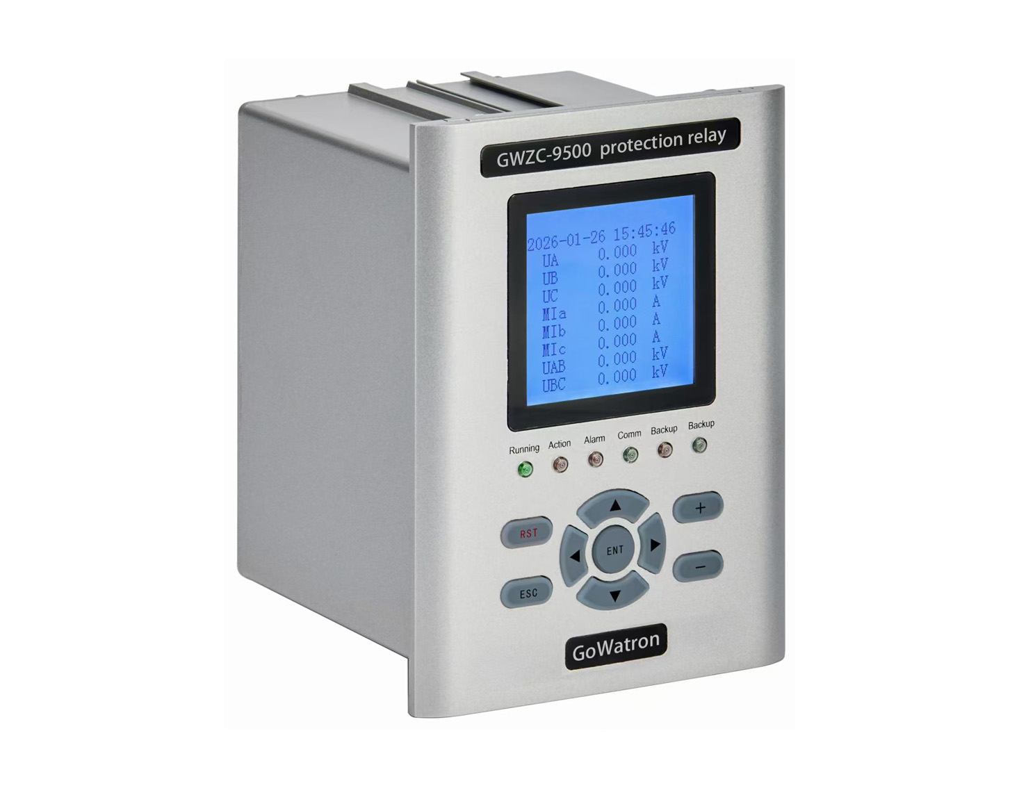
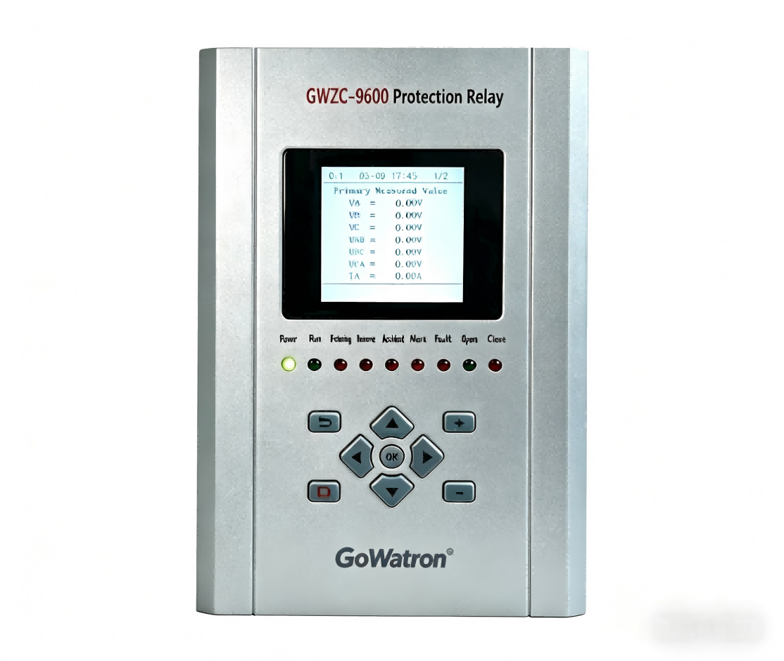
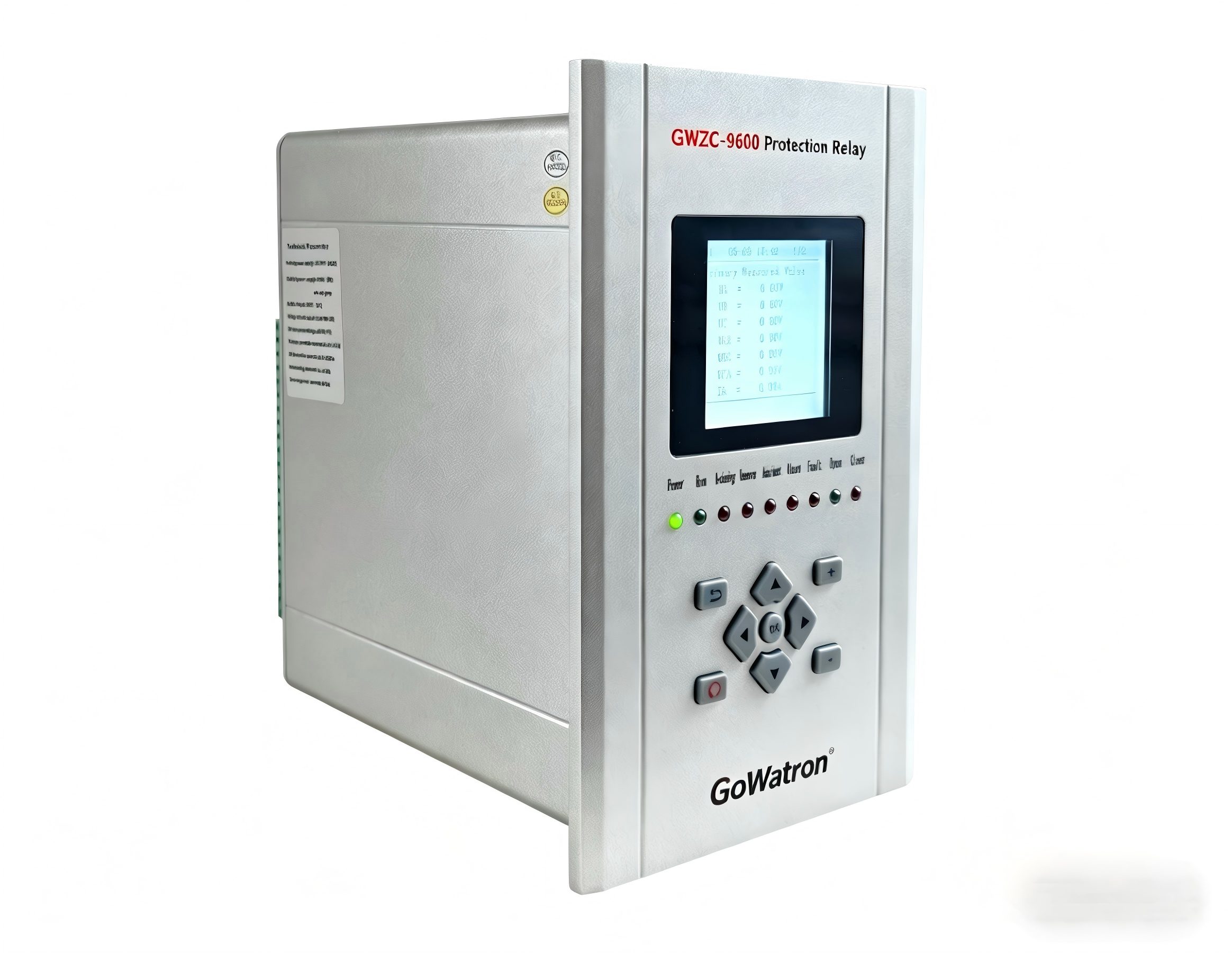
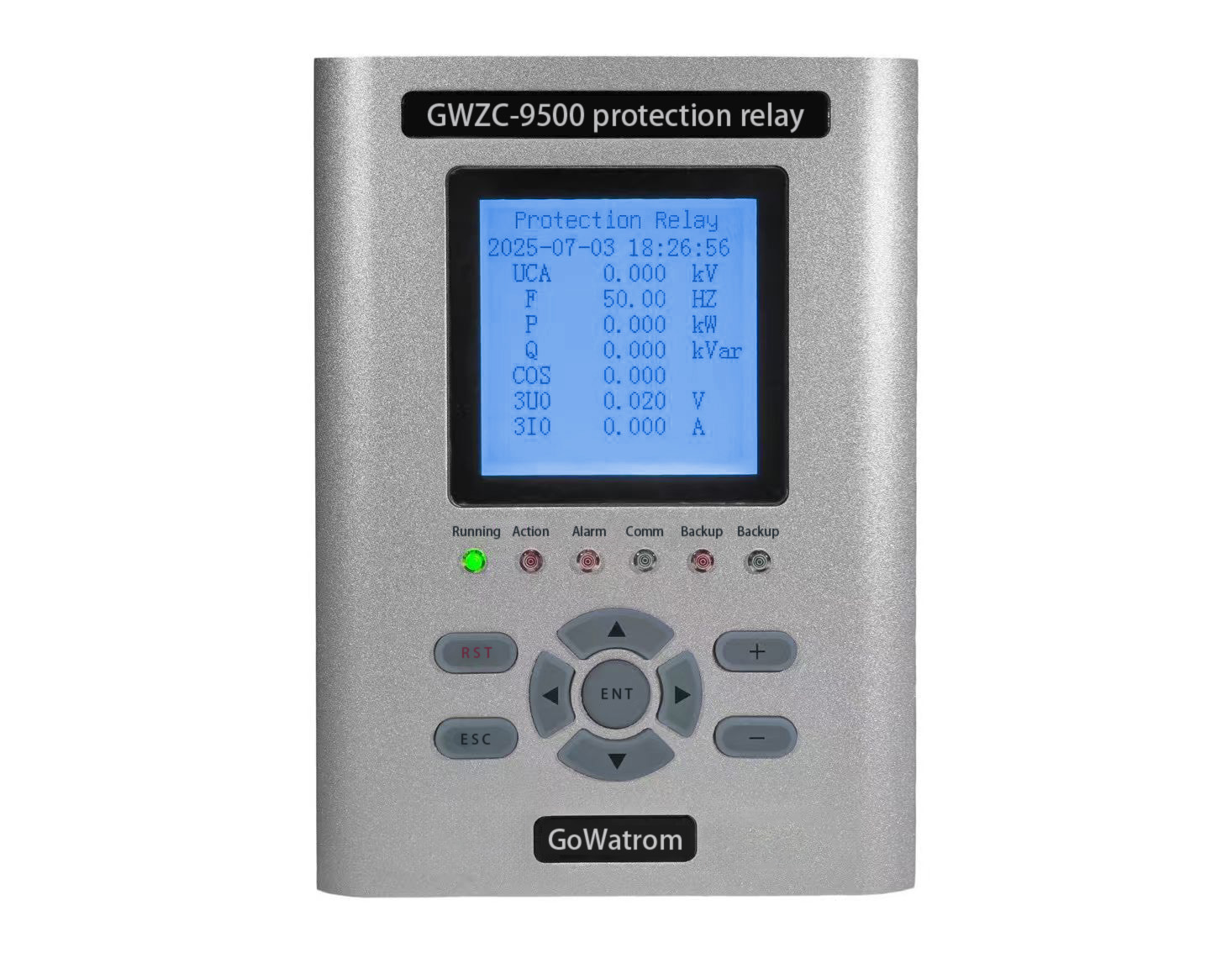
​​Introduction to Digital Motor Protection Relay​

          A digital motor protection relay is an intelligent protection device that uses microprocessor technology to monitor and protect motors from various electrical faults.

Working Principle of Digital Motor Protection Relay​

          ​Signal Acquisition: Real-time monitoring of motor operating parameters via current transformers (CTs) and voltage transformers (VTs)

​          Digital Processing: Microprocessor digitizes and analyzes the collected signals

          ​​Algorithm-Based Judgment: Built-in protection algorithms (overcurrent, undervoltage, imbalance, etc.) assess operating conditions

          ​​Output Control: Triggers relay output to disconnect the circuit upon detecting abnormalities

Application Scope of Digital Motor Protection Relay​

Protection of three-phase AC motors
          ​Voltage levels: Typically suitable for 380V–10kV systems
          ​Power range: From a few kilowatts to several megawatts
          ​Industrial applications: Pumps, fans, compressors, conveyors, etc.

​Key Functions of Digital Motor Protection Relay​

1.Basic Protection Functions:
          ​Overload protection (inverse-time characteristic)
          ​Short-circuit protection (instantaneous or time-delayed)
          ​Phase loss/imbalance protection
          ​Ground fault protection

2.​Advanced Protection Features:
          ​Locked-rotor protection
          ​Under/overvoltage protection
          ​Excessive start-time protection
          ​Thermal overload protection (based on I²t algorithm)

​3.Monitoring Capabilities:
          ​Current/voltage display
          ​Power/power factor monitoring
          ​Operating time recording
          ​Fault logging and event storage

​Practical Recommendations for Digital Motor Protection Relay​

​1.Selection Criteria:
          ​Verify motor-rated parameters (voltage, current, power)
          ​Choose appropriate protection class based on environment (e.g., IP20/IP65)
          ​Consider communication needs (Modbus, Profibus, etc.)

​2.Installation & Commissioning:
          ​Set protection parameters correctly (refer to motor nameplate data)
          ​Test protection functions (simulate faults to verify reliability)
          ​Regularly calibrate protection settings (recommended annually)

Product recommendations More
GWZC-9812 Distance protection relay(21 | 21G | 21FL)
detail
GWZC-9890D Anti-islanding protection relay(AIP)
detail
GWZC-9651 VT (Voltage Transformer) Protection Relay
detail
GWZC-9661 Automatic Transfer Switch (ATS)​​
detail
GWZC-9641 Capacitor protection relay
detail
Technical More
Motor protection relay Side View
Thermistor Motor Protection Relay: Principle, Application, and Troubleshooting​
Thermistor Motor Protection Relay​ monitors motor winding temperature in real-time using PTC/NTC thermistors, triggering protection (alarm or power cutoff) against overheating. It is suitable for critical equipment like servo and high-voltage motors, effectively preventing insulation damage and burnout failures.
2025/07/09
GWZC-9886 Generator Backup Protection Relay
Generator Loss-of-Excitation Protection
Generator loss-of-excitation protection serves as a critical defense against generator excitation current failure caused by excitation system faults. As vital protection against system oscillations, terminal equipment damage, and reverse flow of reactive power during asynchronous operation.
2025/07/08
GWZC-9886 Generator Backup Protection Relay
Working principle, function, and setting calculation for the generator 100% stator earth fault protection.
Generator 100% stator earth fault protection overcomes traditional coverage limitations by combining two complementary methods. The third-harmonic voltage principle monitors the neutral-to-terminal voltage ratio to detect faults near the neutral, triggering when this ratio falls below a typical threshold of 0.3-0.5. Simultaneously, the low-frequency injection method introduces a 20Hz signal to measure insulation resistance across the entire winding, operating if resistance drops below pre-set thresholds (typically 1-5 kΩ). This dual approach ensures complete stator coverage without dead zones, provides high sensitivity for kΩ-range faults, and offers redundancy. Protection settings are derived from security margins applied to measured normal operating parameters, including harmonic voltage ratios and maximum unbalanced voltage, making it essential for large generator security.
2025/07/07
Line protection relay Side View
The working principle, function, and setting calculation of zero-sequence voltage protection.
Zero-sequence voltage protection is a vital protection scheme in power systems specifically designed for ground faults, particularly single-phase-to-ground faults. It is widely employed in systems with an ungrounded neutral, a neutral grounded via an arc-suppression coil (Petersen coil), or a low-resistance grounded neutral. The following provides a detailed explanation from three aspects: principle, function, and setting calculation.
2025/07/04
Inquiry Consultation
+86-17621210051
+86-17621210051
+86-17621210051
+86-17621210051
home product email
live chat
my