Capacitor unbalanced current protection is a critical technology in power systems used to detect and protect against internal faults within capacitor banks. It operates by monitoring the changes in unbalanced current at the neutral point or bridge circuit of the capacitor bank, promptly isolating faults to prevent their escalation.
Working Principle of Capacitor Unbalanced Current Protection
Capacitor unbalanced current protection primarily operates based on the principle of current unbalance monitoring. Its specific implementation is closely related to the wiring configuration of the capacitor bank:
Double-Star Connection: In this configuration, a current transformer (CT) is connected between the neutral points of two parallel star-connected capacitor banks. During normal operation, the potentials of the two neutral points are essentially equal, resulting in a very small unbalance current flowing through the neutral connection. If a capacitor unit in one phase fails (e.g., element breakdown or fuse operation), the capacitance value of that phase changes, creating a potential difference between the two neutral points. This generates a significant zero-sequence unbalance current in the neutral connection. The Capacitor Protection Relay detects this current to identify the fault.
Bridge-Type Differential Protection: For bridge-connected capacitor banks, protection is achieved by monitoring the current difference in the bridge arms. When a portion of the capacitors fail, it causes current unbalance in the bridge circuit, triggering the protection.
Comparison of H-Bridge and Δ Configurations:
H-Bridge Connection: After a capacitor unit in a single leg is short-circuited, the operating setting of the unbalance protection must be determined based on the overvoltage level of the remaining healthy units. Its operating setting is relatively low, making it less resistant to interference.
Delta (Δ) Connection: Utilizes current transformers to measure differential current. In the event of partial capacitor failure, it can better utilize the remaining capacity of the faulty capacitor, and the insulation requirements for the current transformers are relatively lower.
Function and ANSI Codes of Capacitor Unbalanced Current Protection
The core function of unbalanced current protection is to detect internal localized faults within the capacitor bank, preventing fault expansion that could lead to complete bank failure or more severe system incidents. Its main functions include:
Fault Detection and Alarm: Triggers an alarm signal when internal components of the capacitor bank fail.
Preventing Overvoltage Propagation: Promptly disconnects the faulty section to prevent healthy capacitors from damage due to excessive voltage.
Ensuring System Stability: Maintains the harmonic filtering capability and reactive power compensation of the power system.
According to ANSI/IEEE standards, capacitor unbalance protection is typically designated by function code 46 for negative sequence or unbalance current protection. Specific implementations for different connection types include:
Neutral Unbalance Protection for Double-Star Connection (ANSI 46NS)
Bridge Differential Protection (ANSI 46B)
Capacitor Unbalanced Current Protection Setting Calculation
The core principle of setting calculation is: Ensuring reliable operation during faults while securely avoiding operation during normal unbalance conditions. Calculation formulas vary depending on the capacitor bank’s connection type and internal structure.
Double-Star Connection Unbalance Protection Setting
1. Operating Current Value Calculation:
Iop=K⋅Irated/Ksens.Mb.NCT
Where:
Iop: Protection operating current setting value
K: Number of capacitor units removed due to the fault
Irated: Rated current of a single capacitor unit
Ksens: Sensitivity coefficient (typically 1.25–1.5)
Mb: Number of parallel capacitor units per series group in one arm of the double-star connection
NCT: Current transformer ratio
2. Verification of Normal Unbalance Current:
Iop>I0,unb
Where I0,unb is the measured unbalance current between neutral points during normal operation.
Bridge Differential Protection Setting
1. Differential Operating Current Value Calculation:
ΔIop=K⋅Irated/Ksens⋅NCT
Where ΔIop is the operating current value for the bridge differential protection.
General Setting Principles
Secure Avoidance of Normal Unbalance: The setting value must be greater than the unbalance current during normal capacitor bank operation. Typically, the measured normal unbalance should not exceed 10% of the setting value.
Setting Based on Overvoltage Level: The operating value should ensure that the voltage across healthy capacitors does not exceed the permissible limit (usually 1.1–1.15 times the rated voltage) under any internal fault condition.
Sensitivity Verification: The protection device must have sufficient sensitivity for the minimum fault condition, with a sensitivity coefficient generally not less than 1.25.
Time Delay Setting: To prevent false operations, a time delay (typically 0.1–0.2 seconds) is usually set to ride through transients during capacitor bank energization.
Summary of Key Points
Core Principle: Protects the capacitor bank by monitoring the unbalance current caused by internal faults.
Main Function: Prevents fault expansion and ensures system safety. Corresponding ANSI codes are 46 and its variants.
Setting Core: Ensures sensitive operation during faults while reliably avoiding operation during normal conditions and various transients like switching events.
We hope this explanation helps you fully understand capacitor unbalanced current protection. If you need analysis for a specific type of capacitor bank or wish to explore more detailed setting calculation examples, please feel free to specify your requirements further.
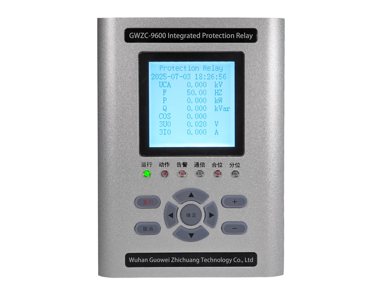
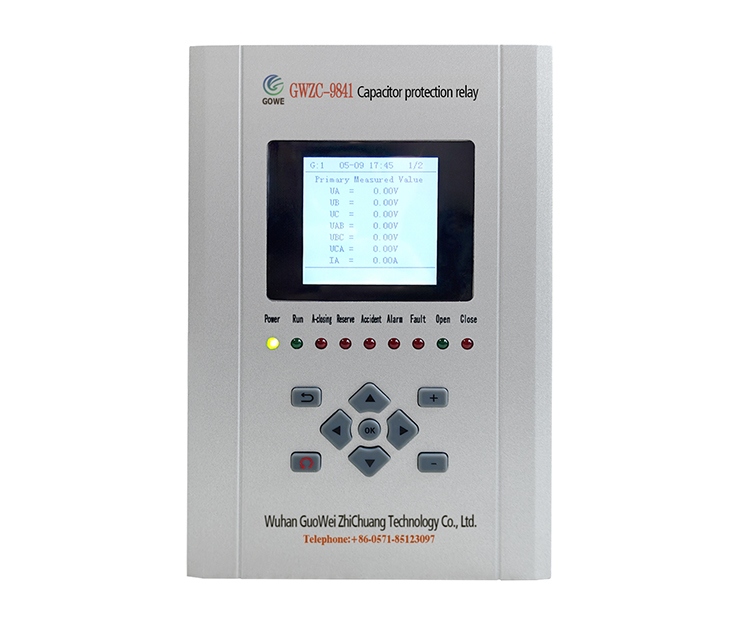
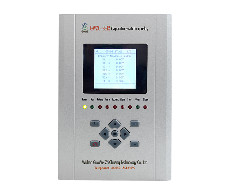
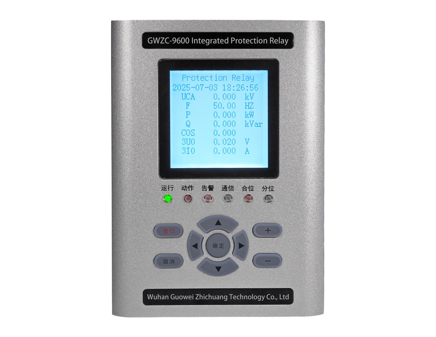
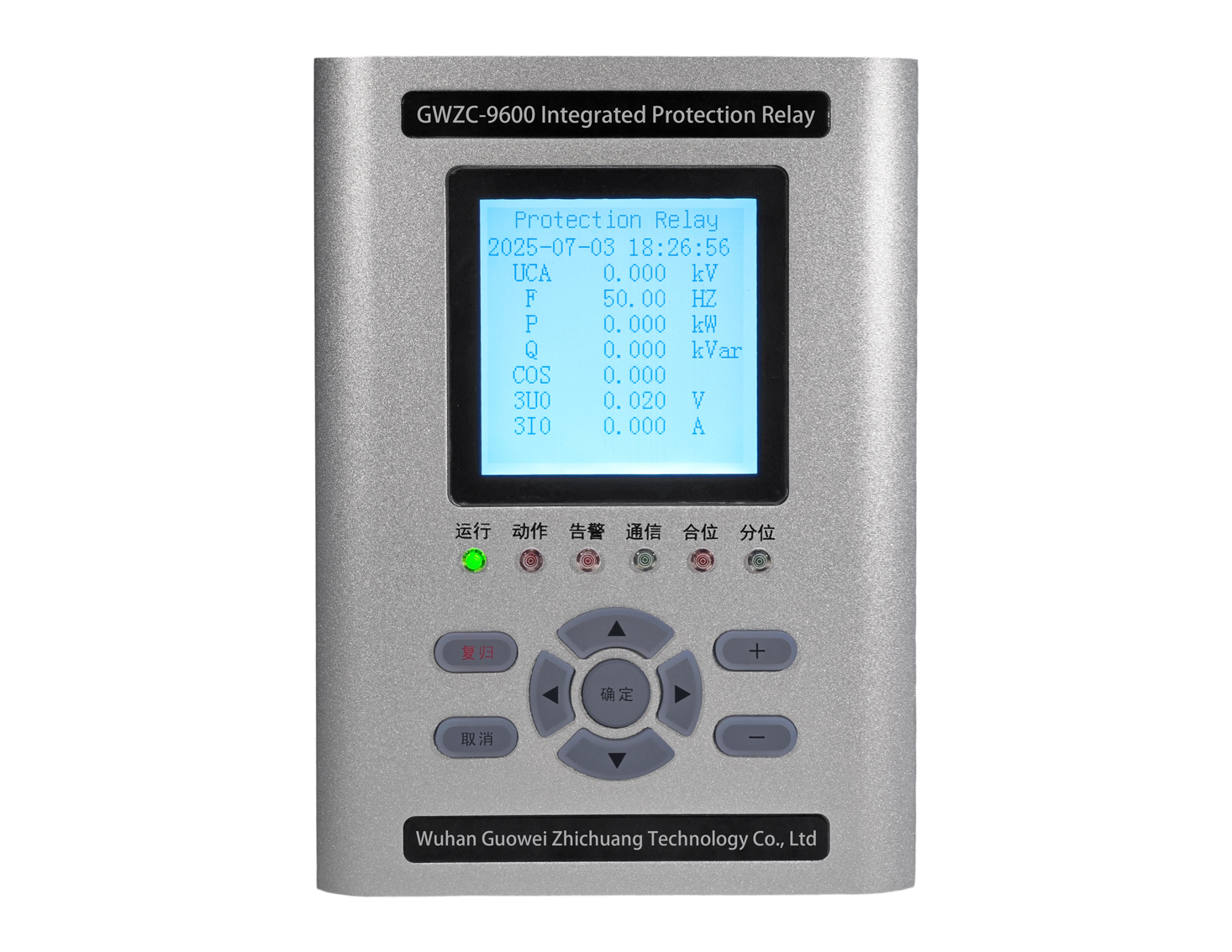
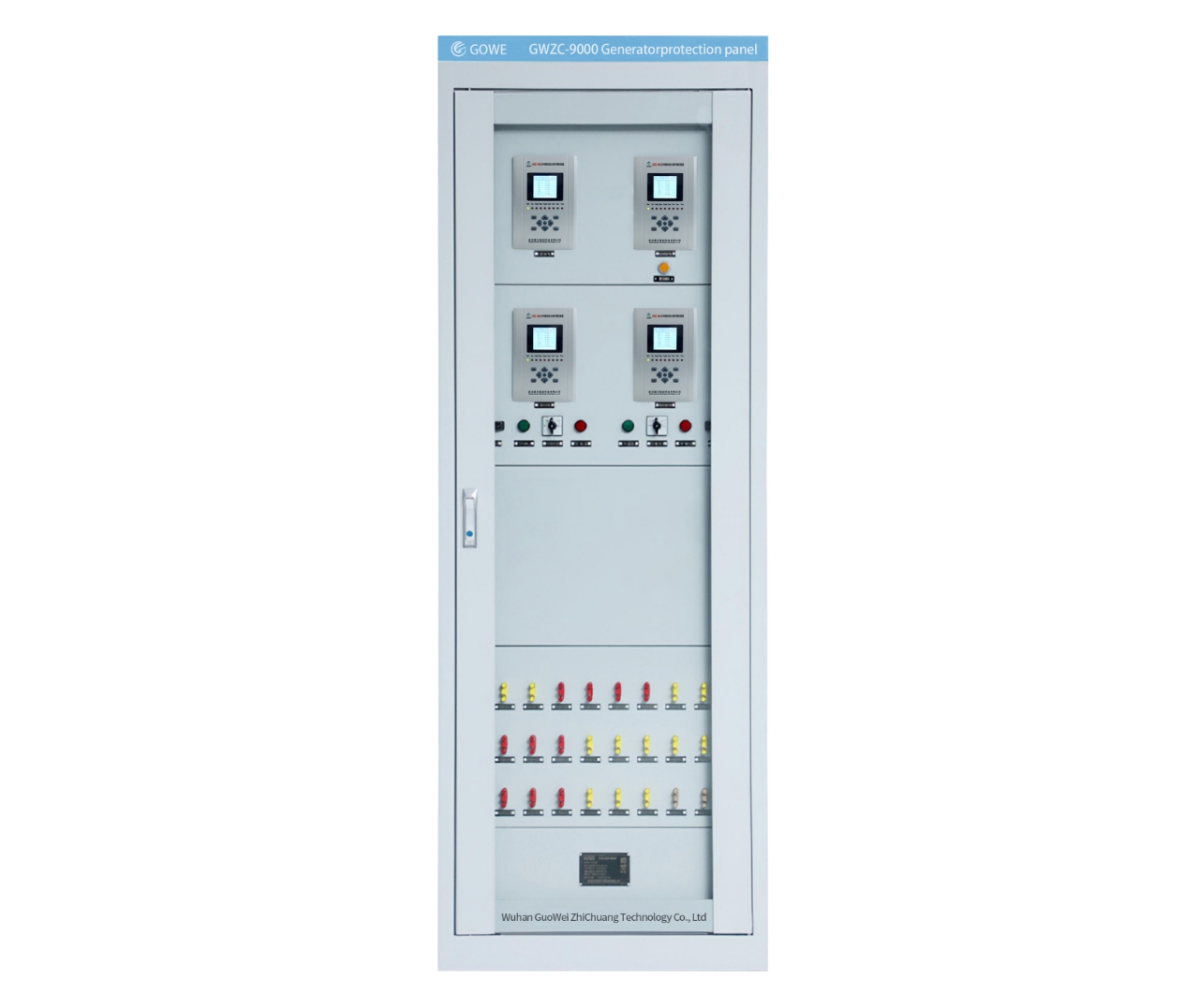
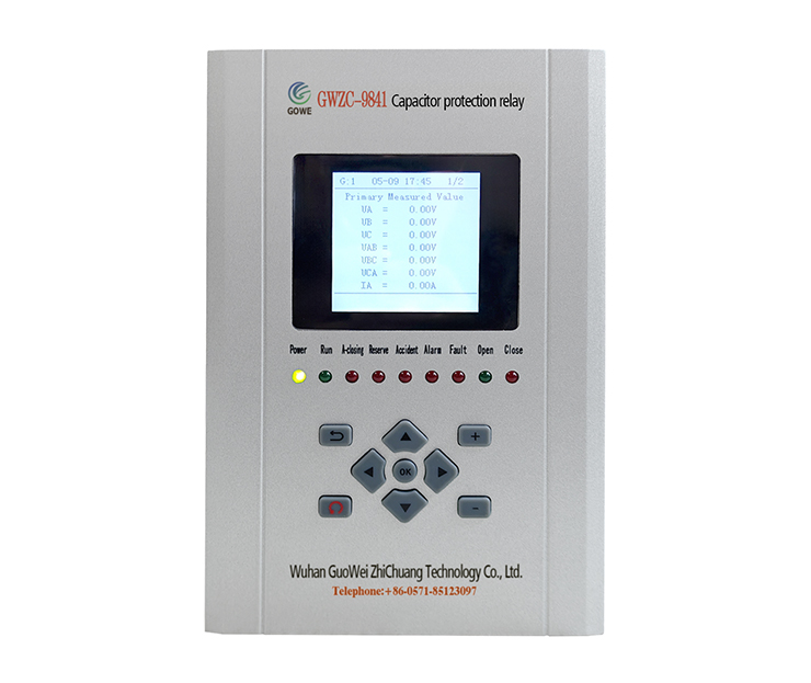
Our company’s GWZC-9641 Capacitor Protection Relay and GWZC-9841 Capacitor Protection Relay are both equipped with unbalance current protection functions. We welcome your inquiries and purchases.
