1. Capacitor Unbalance Voltage Protection /Working Principle
Capacitor Unbalance Voltage Protection is used to monitor the voltage distribution among individual units within a capacitor bank, particularly in series-connected banks. Its operating principle is based on Kirchhoff’s Voltage Law and capacitor voltage division. Under normal operating conditions, the voltage across each unit in the bank is relatively balanced, resulting in a minimal unbalance voltage. When a capacitor unit fails (e.g., internal short circuit, open circuit, or performance degradation), the voltage distribution becomes unequal, generating a significant unbalance voltage.
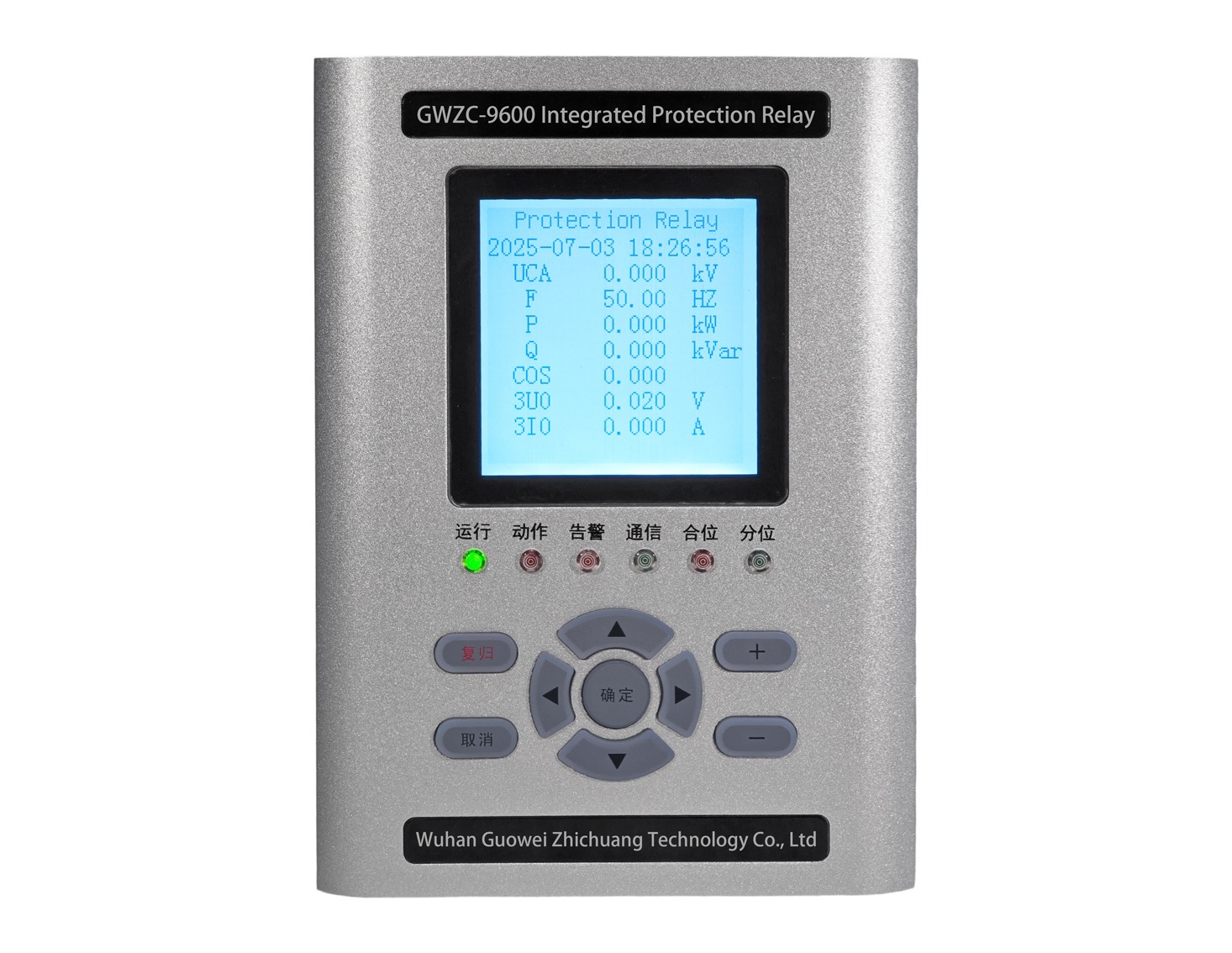
The protection Relay measures the unbalance voltage at the bank’s neutral point or a specific point using a Voltage Transformer (VT) or a voltage divider. Typically, for grounded system neutrals or ungrounded system floating neutrals, the VT measures the voltage between the neutral point and ground (i.e., zero-sequence voltage or residual voltage). If the measured unbalance voltage exceeds a predefined setpoint, the protection device triggers an alarm or a trip signal to isolate the faulty capacitor unit, preventing further damage or cascading failures.
2. Capacitor Unbalance Voltage Protection /Function
Primary Functions:
Detect internal faults within capacitor units (e.g., short circuits, open circuits, or capacitance value changes).
Prevent damage to the capacitor bank due to overvoltage or overheating, avoiding chain failures.
Maintain power system stability and reactive power compensation capability.
International ANSI Code: The standard ANSI device number for this protection function is 60 (Voltage Balance Protection). In some configurations, if neutral point voltage displacement is measured, 59N (Neutral Displacement Voltage Protection) might be used. However, for capacitor unbalance voltage protection, ANSI 60 is the primary code.
3. Capacitor Unbalance Voltage Protection /Setting Calculation
The setting calculation must be based on the specific configuration of the capacitor bank (e.g., number of series units per phase, number of parallel strings), system voltage, and capacitor parameters. The general calculation steps and formulas are as follows:
Basic Parameters:
N: Number of series-connected units per phase.
M: Number of parallel strings per phase.
Vphase: System phase voltage (rated value).
C: Rated capacitance of each individual capacitor unit.
Vunit: Rated voltage of each capacitor unit (typically Vunit=Vphase/N
When one capacitor unit fails short-circuited, the voltage redistributes across the remaining healthy units in the faulty string. The faulty string, now with N−1 units, will bear the full phase voltage, altering the total capacitance of that string and generating an unbalance voltage.
For a typical neutral-point unbalance voltage protection scheme, the unbalance voltage Vunb can be estimated using:
Vunb=Vphase×[1/N(N-1)]*K
where K is a coefficient dependent on the bank structure (e.g., number of parallel strings). More precise calculations may require detailed bridge circuit analysis or consideration of the VT ratio.
Setting Value Determination:
The setpoint Vset should be greater than the maximum unbalance voltage under normal operating conditions (including measurement errors and transient effects) but less than the unbalance voltage generated when a single unit fails. Typically:
Vset=Ksafe×Vunb,fault
where:
Vunb,fault is the calculated unbalance voltage for a single unit failure.
Ksafe is a safety factor, usually between 0.5 and 0.8, to prevent maloperation while ensuring sensitivity.
Furthermore, the setting must account for the Voltage Transformer ratio (VTratio). Therefore, the actual secondary side setting is:
Vset,secondary= Vset/VTratio
Example Calculation:
Assume a capacitor bank with 10 series-connected units per phase (N=10), a system phase voltage Vphase=13.8kV and a VT ratio of 100:1. If one unit shorts:
Vunb,fault≈ 13.8kV/10×(10−1)=0.153kV=153V
Using a safety factor Ksafe=0.7
Vset=0.7×153V=107.1V
Secondary side setting:
Vset,secondary = 107.1V/100=1.071V
In practical engineering, the final setpoint may be adjusted based on manufacturer recommendations, system testing, and considerations for temperature variations and aging.
Notes
This protection function must be coordinated with Overvoltage Protection (ANSI 59) and Overcurrent Protection (ANSI 50/51).
For ungrounded capacitor banks, unbalance voltage protection might be implemented via a bridge circuit, with similar calculation principles.
Setting calculations should ideally be verified using power system analysis software or detailed circuit models to ensure accuracy.
