Back to smartelemfg Home
Contact us Merchants settle in
Back to smartelemfg Home
Home -Technical

Application of Pilot Directional Comparison Protection in Distribution Automation: Communication Channel and Criterion Design

Source: 2025-07-23 15:56:47

1. Introduction to Pilot Protection Systems

          Pilot directional comparison protection represents a communicationbased protection scheme that compares fault direction information from both ends of protected lines for accurate fault location identification.

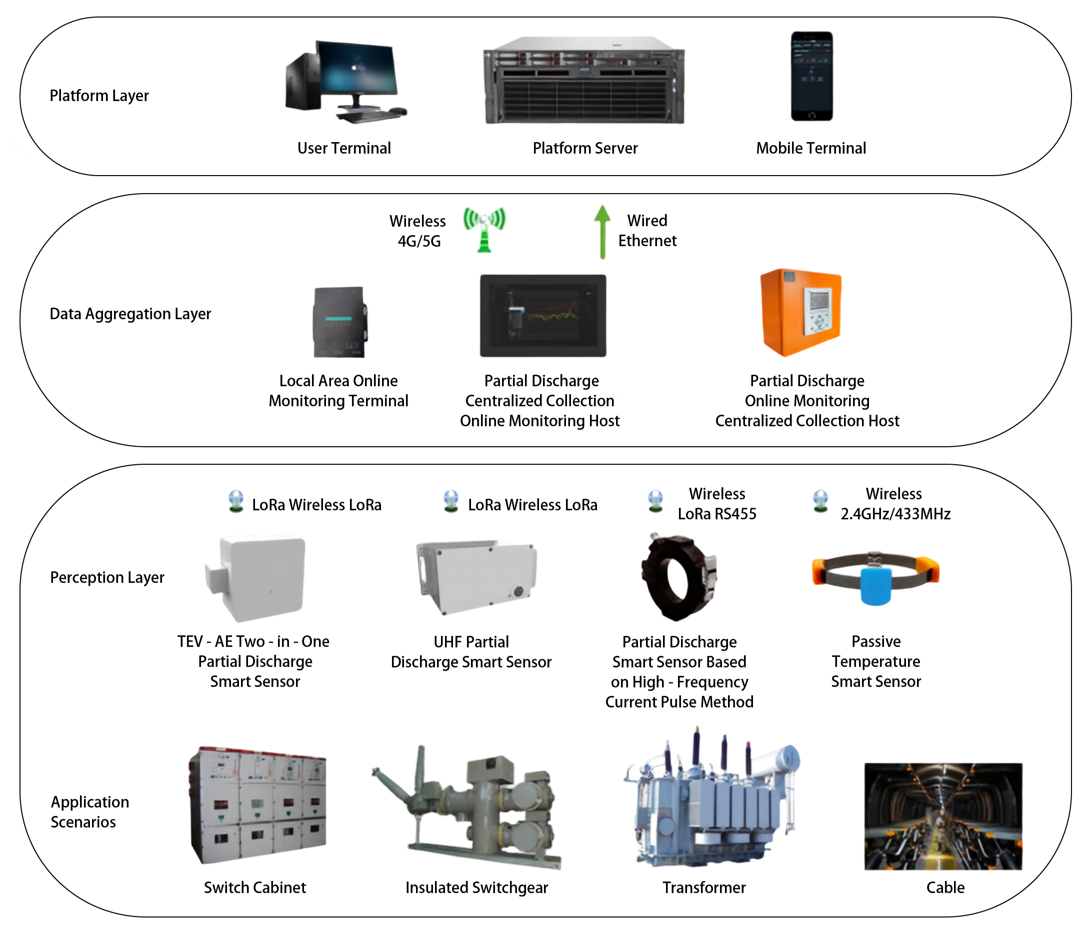
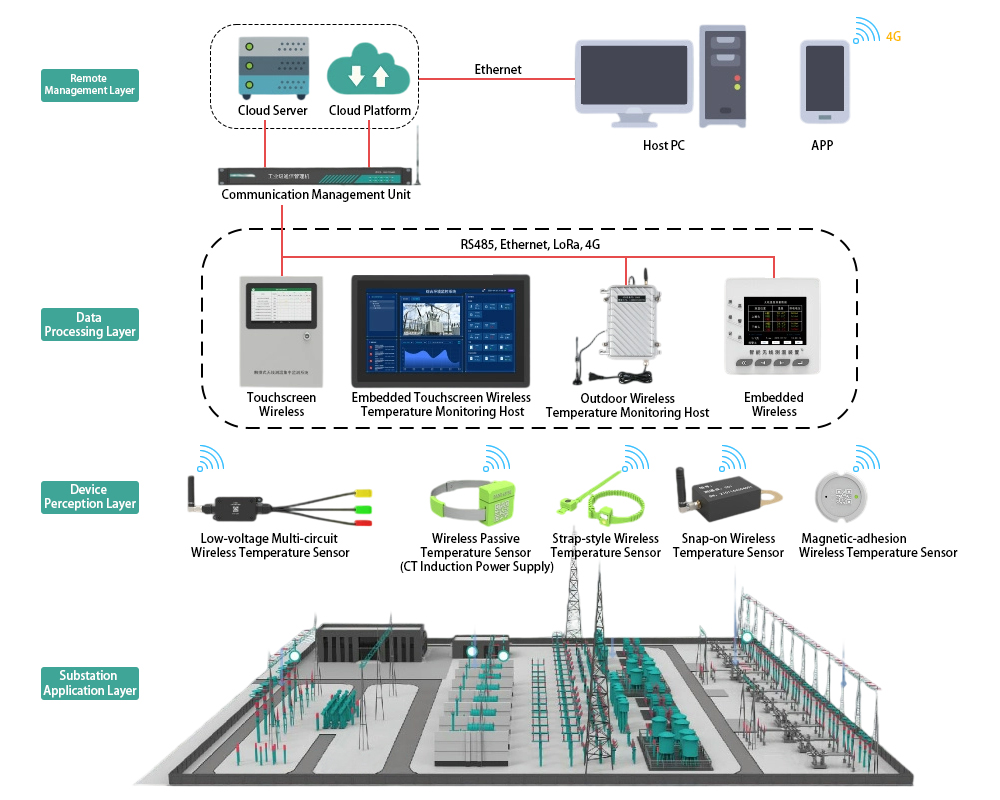
2. Communication Channel Requirements

          Modern distribution networks utilize fiber optic (preferred), power line carrier, or wireless channels meeting IEC 61850 standards with ≤20ms transmission delay. Redundant channel configurations enhance reliability.

3. Protection Criterion Design Principles

          The directional element employs sequence component analysis (90° connection method) with the operating characteristic : θ = arg(Ú/Í). Faults are identified when 90°<θ<90° at one terminal with opposite direction at the other end.

4. Smart Grid Applications

This protection scheme proves particularly effective for:

  • 10-35kV loop/meshed distribution networks
  • Highimpedance earth faults
  • Distributed generation integration scenarios

5. Implementation Guidelines

Key deployment considerations include:

  • Fiber optic channel selection (EPON recommended)
  • Protection relay configuration (IEC 61850 GOOSE support)
  • Typical settings: 30° sensitivity angle, 1.2×load current pickup

6. Safety & Maintenance Protocols

Critical safety measures involve:

  • Disabling protection during channel testing
  • Proper fiber optic handling procedures
  • Comprehensive functional testing after setting changes

7. Future Development Trends

          Integration with Feeder Automation systems is evolving toward Intelligent Distributed FA solutions capable of sub200ms fault isolation in advanced distribution networks.

Product recommendations More
GWZC-9913 FO Line Diff Relay(87L)
detail
GWZC-9586 Low-voltage generator protection relay
detail
GWZC-9605 Cable insulation monitoring device (IMD)​​(ANSI 64)
detail
GOWE-9000 Partial discharge online monitoring system
detail
GOWE-9000 Wireless Temperature Monitoring System for Substations
detail
Technical More
Generator Protection Panel
Generator Protection Relay Panel : Composition and Function
Integrating protection, measurement, and communication, the Generator Protection Relay Panel can realize the protection and control of various units, enabling unattended or minimally attended operation. It can achieve generator differential protection, rotor earth fault protection, stator earth fault protection, excitation protection, overcurrent protection, overvoltage protection, overload protection, backup protection, etc.
2025/11/25
Main Transformer-Protection Panel
Transformer Protection Relay Panel:Composition and Function
Transformer Protection Relay Panel is primarily used in automation systems for substations and distribution stations in power systems of 11kV, 33kV, 132kV and above. Its main function is to ensure that the transformer can promptly trip the faulty circuit in case of overload, short circuit, gas relay activation, and other abnormal operating conditions, thereby protecting the main transformer from damage and preventing the expansion of faults.
2025/11/24
Feeder Protection Relay
Common Protection Functions for Feeder Protection Relays?
Feeder protection relays are a type of line protection relay and serve as critical devices in distribution systems for protecting power cables (feeders). They integrate multiple protection functions to achieve comprehensive, reliable, and selective protection. Below are the commonly used protection functions of feeder protection relays, along with their corresponding ANSI codes.
2025/11/14
Transformer protection relay
Transformer Differential Protection(ANSI 87T): Working Principle, Function, and Setting Calculation
The working principle of the Transformer Differential Protection Relay is based on Kirchhoff's Current Law. This law states that the sum of currents entering a node is zero. Ideally, for a healthy (non-faulted) transformer, the current entering the primary winding should equal the current leaving the secondary winding (after accounting for the transformer's turns ratio and phase shift).
2025/11/12
Inquiry Consultation
+86-17621210051
+86-17621210051
+86-17621210051
+86-17621210051
home product email
live chat
my