Back to smartelemfg Home
Contact us Merchants settle in
Back to smartelemfg Home
Home -Technical

Analysis of Single-Phase Ground Fault in Ungrounded Neutral System

Source: Maxwell He 2025-07-28 14:19:35

1. Fault Characteristics

  • Voltage Changes: 

The fault phase voltage drops to zero (metallic grounding), while nonfault phases rise to line voltage (√3 times phase voltage). Line voltages remain balanced, ensuring threephase load operation.

  • ZeroSequence Voltage:

A zerosequence voltage U0 = {UA + UB + UC}/3  appears, equal to the normal phase voltage (e.g., ~5.77kV in a 10kV system).

  • Capacitive Current:

The fault current consists of capacitive currents from nonfault phases, calculated as ( 3ω C Uϕ​) (where ( C ) is phase-to-ground capacitance).

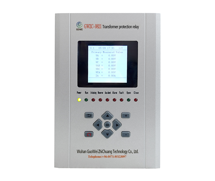
Transformer protection relay devices can detect abnormal zerosequence currents, aiding fault identification.

2. Transient Process Analysis

  • HighFrequency Oscillation:

Instantaneous capacitive discharge generates highfrequency transient currents (hundreds of Hz to kHz), with amplitudes 5-10 times the steadystate current.

  • Arcing Risks:

Intermittent arcing may cause overvoltages (up to 3.5× phase voltage), threatening insulation.

A Transformer protection relay with arc detection can prevent equipment damage.

3. SteadyState Analysis

  • Neutral Point Displacement:

The neutral voltage shifts from zero to phase voltage, opposing the fault phase (e.g., UN = -UA for an A-phase fault).

  • Capacitive Current Distribution:

Non-fault phase currents (B, C) have a 120° phase difference, summing at the fault point with a 90° lead over zero-sequence voltage.

4. Protection & Detection

  • Insulation Monitoring:

Detects zerosequence voltage via PT opendelta windings (threshold: 15-30% of phase voltage).

  • Fault Line Selection:
    • Transient Signal Method: Uses initial current polarity or wavelet analysis.
    • Harmonic Method: Tracks 5th harmonic direction.
    • Signal Injection: Active frequencybased tracing.

Transformer protection relay systems enhance accuracy in fault localization.

5. Handling & Risks

  • Permissible Duration:

Systems may operate for 1-2 hours but require prompt fault clearance to avoid phase-to-phase faults.

  • Overvoltage Risk:

Highresistance grounding can cause resonant overvoltages, necessitating arc suppression coils (tuned to ±5% detuning).


6. Simulation Key Parameters

  • Ground Capacitance  C :

~5-10nF/km (overhead lines), ~50-200nF/km (cables).

  • Example Calculation:

For a 10kV system with 20km lines ( C = 0.1u F ), steadystate fault current ( IC ≈ 5.5A ).

Transformer protection relay settings must account for capacitive current thresholds.

          Ungrounded systems rely on capacitive current behavior during singlephase faults. Modern grids may use resistance grounding or arc suppression coils, but traditional ungrounded systems suit lowcapacitance networks (e.g., rural grids). Analysis requires realtime monitoring and Transformer protection relay integration for safety.
Product recommendations More
GWZC-9621 Distribution transformer protection relay
detail
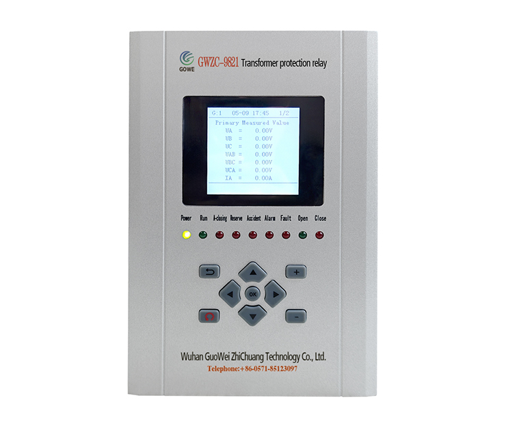
GWZC-9821 Transformer protection relay
detail
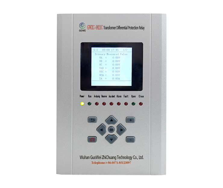
GWZC-9821C Transformer Differential Protection Relay (87T)
detail
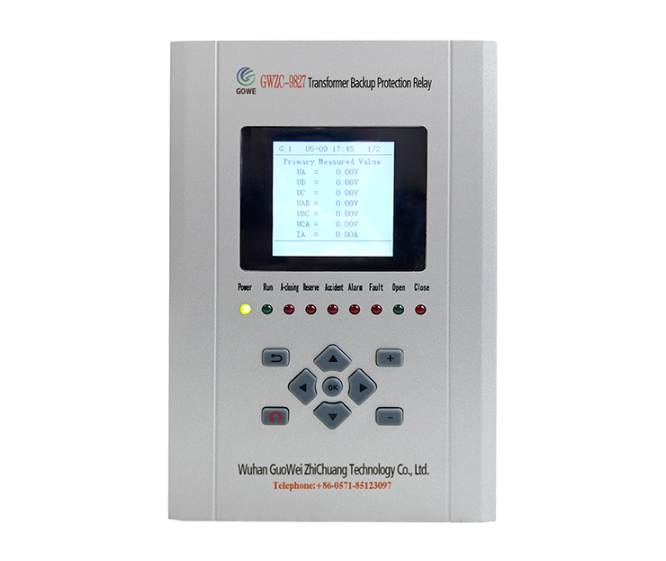
GWZC-9827 Transformer Backup Protection Relay
detail
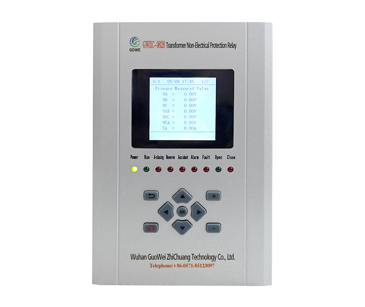
GWZC-9828 Transformer Non-Electrical Protection Relay
detail
Technical More
Generator Protection Panel
Generator Protection Relay Panel : Composition and Function
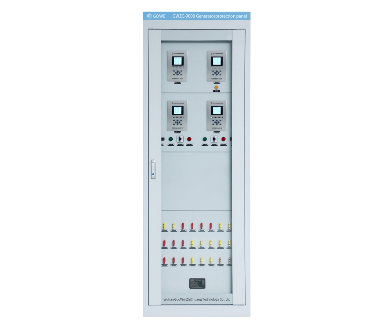
Integrating protection, measurement, and communication, the Generator Protection Relay Panel can realize the protection and control of various units, enabling unattended or minimally attended operation. It can achieve generator differential protection, rotor earth fault protection, stator earth fault protection, excitation protection, overcurrent protection, overvoltage protection, overload protection, backup protection, etc.
2025/11/25
Main Transformer-Protection Panel
Transformer Protection Relay Panel:Composition and Function
Transformer Protection Relay Panel is primarily used in automation systems for substations and distribution stations in power systems of 11kV, 33kV, 132kV and above. Its main function is to ensure that the transformer can promptly trip the faulty circuit in case of overload, short circuit, gas relay activation, and other abnormal operating conditions, thereby protecting the main transformer from damage and preventing the expansion of faults.
2025/11/24
Feeder Protection Relay
Common Protection Functions for Feeder Protection Relays?
Feeder protection relays are a type of line protection relay and serve as critical devices in distribution systems for protecting power cables (feeders). They integrate multiple protection functions to achieve comprehensive, reliable, and selective protection. Below are the commonly used protection functions of feeder protection relays, along with their corresponding ANSI codes.
2025/11/14
Transformer protection relay
Transformer Differential Protection(ANSI 87T): Working Principle, Function, and Setting Calculation
The working principle of the Transformer Differential Protection Relay is based on Kirchhoff's Current Law. This law states that the sum of currents entering a node is zero. Ideally, for a healthy (non-faulted) transformer, the current entering the primary winding should equal the current leaving the secondary winding (after accounting for the transformer's turns ratio and phase shift).
2025/11/12
Inquiry Consultation
+86-17621210051
+86-17621210051
+86-17621210051
+86-17621210051
home product email
live chat
my