Back to smartelemfg Home
Contact us Merchants settle in
Back to smartelemfg Home
Home -Technical

Configuration Principles for Motor Protection Systems​

Source: 2025-07-03 15:40:12


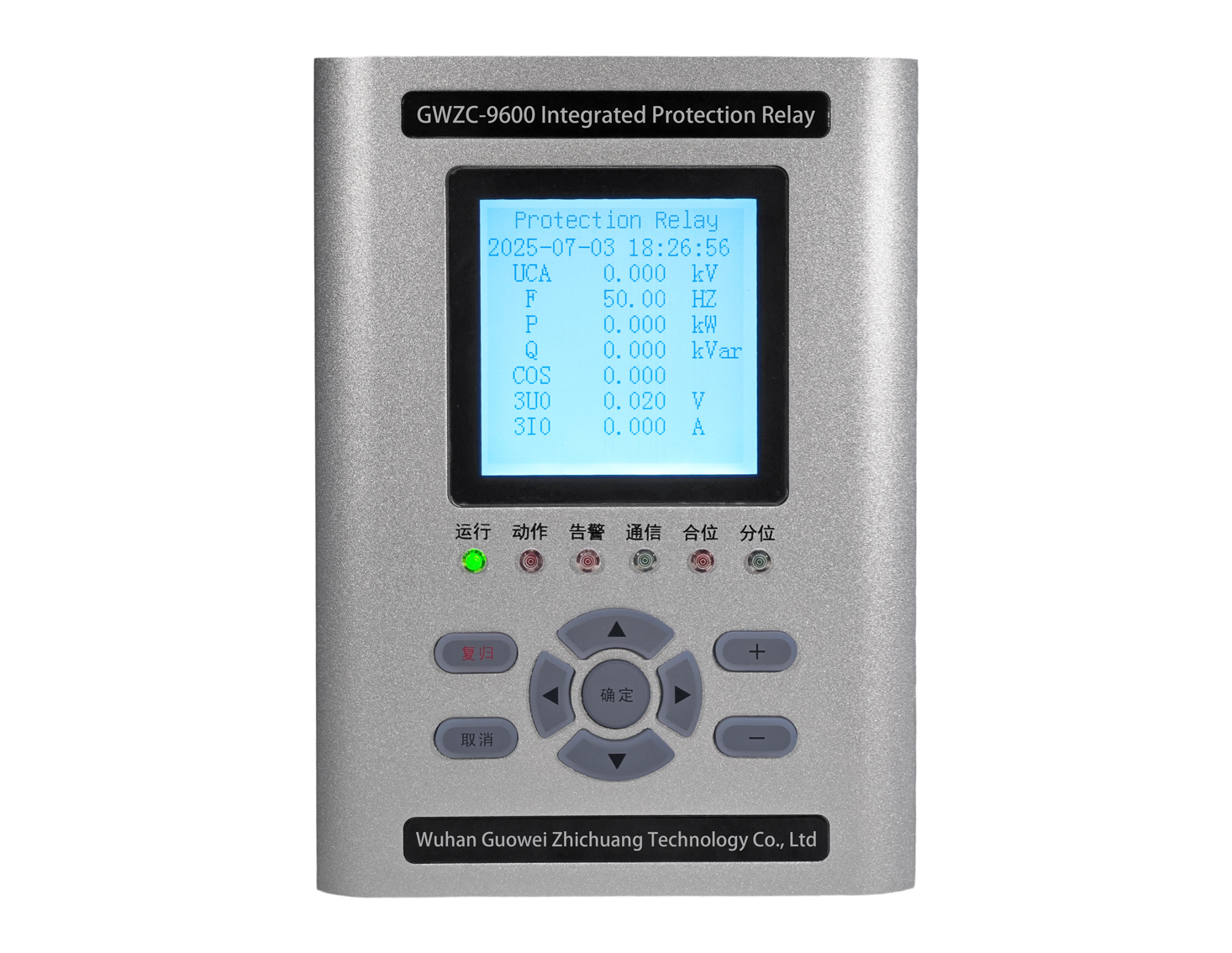
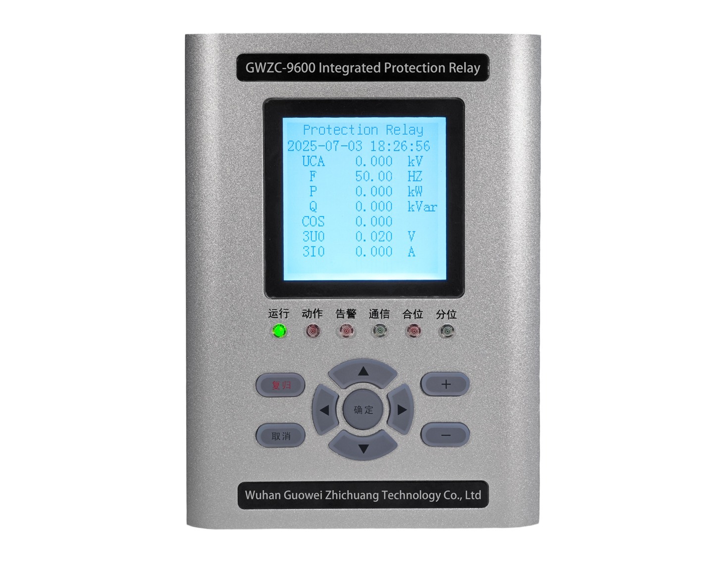
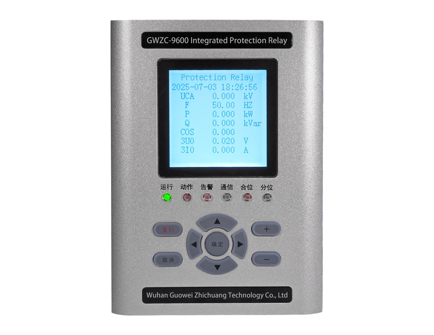
          Electric motors are the most common loads in industrial production, distributed across various voltage levels. This presentation introduces motor protection relays and how to select protection functions.

          Based on IEC 60204-1 and GB 50055 (Design Code for Distribution of Electrical Equipment)

​1. Essential Protection Schemes​

​1.1 Short-Circuit Protection​

​         1.Devices :  Circuit breakers (instantaneous magnetic trip) or fuses
         2.Setting Principle:
                ​         ​         I set=K×Ist
                   Where K = 1.5–2.5 (fast-trip characteristic)

                  I st = motor starting current (typically 6–12 × I N )
          ​3.Requirement: Operation time < motor thermal withstand limit (≤0.1s).

​1.2 Overload Protection​

          1. ​Devices: Thermal relays (e.g., JRS1D series) or electronic protectors
          2. ​Setting Principle:
                  ​         ​         I set =(1.05∼1.2)×I N

                  Note: Ambient temperature compensation required
          3.​Inverse-Time Characteristic : Complies with IEC 60255 curves (Class 10A/20A).

2. Optional Protection Schemes (Application-Specific)​​

Protection Type​ ​Application Scenarios​ Implementation​
​Locked-Rotor Protection​ High-inertia loads (e.g., crushers)

Current threshold (≥2.5 × IN ) with short-time delay

Phase Failure Protection​ Unbalanced systems (>10%) Voltage/current monitoring
Earth Fault Protection​ TN/TT systems (prioritized in damp areas) RCDs (30mA–10A trip range)
​Undervoltage/Overvoltage​ Volatile power grids Voltage relays (±10% U N with time delay)
​Bearing Temperature HV motors/forced-cooling systems PTC thermistors + controllers (trip ≤80°C)

​​3. Enhanced Protection for Special Applications​

3.1 Soft Start/VFD-Driven Motors​

          1.Add di/dt protection to mitigate inrush currents
          2.Install dt/dU filters at VFD output to suppress voltage reflection waves

3.2 Explosive Atmospheres (Ex d/e)​​

          1.Devices must comply with ATEX/IECEx certification
          2.Overload trip time < motor surface ignition time ( t E parameter )

​3.3 Smart Protection Solutions

          ​IoT-based monitoring (vibration + current harmonic analysis) for predictive maintenance


4. Critical Design Considerations​

​4.1 Selectivity Coordination​

          1.Short-circuit protection must operate before overload devices (time/current selectivity)
          2.Avoid curve overlapping between upstream breakers and thermal relays (refer to IEC 60947 coordination charts)

4.2  Sensitivity Verification​

          Minimum short-circuit current must satisfy:
                  I kmin >1.3×I set

​4.3  Safety Compliance​

          1.Always de-energize and verify dead circuit​ before commissioning
          2.Implement LOTO (Lockout-Tagout) procedures per OSHA 1910.147 during maintenance
Product recommendations More
GWZC-9586 Low-voltage generator protection relay
detail
GWZC-9605 Cable insulation monitoring device (IMD)​​(ANSI 64)
detail
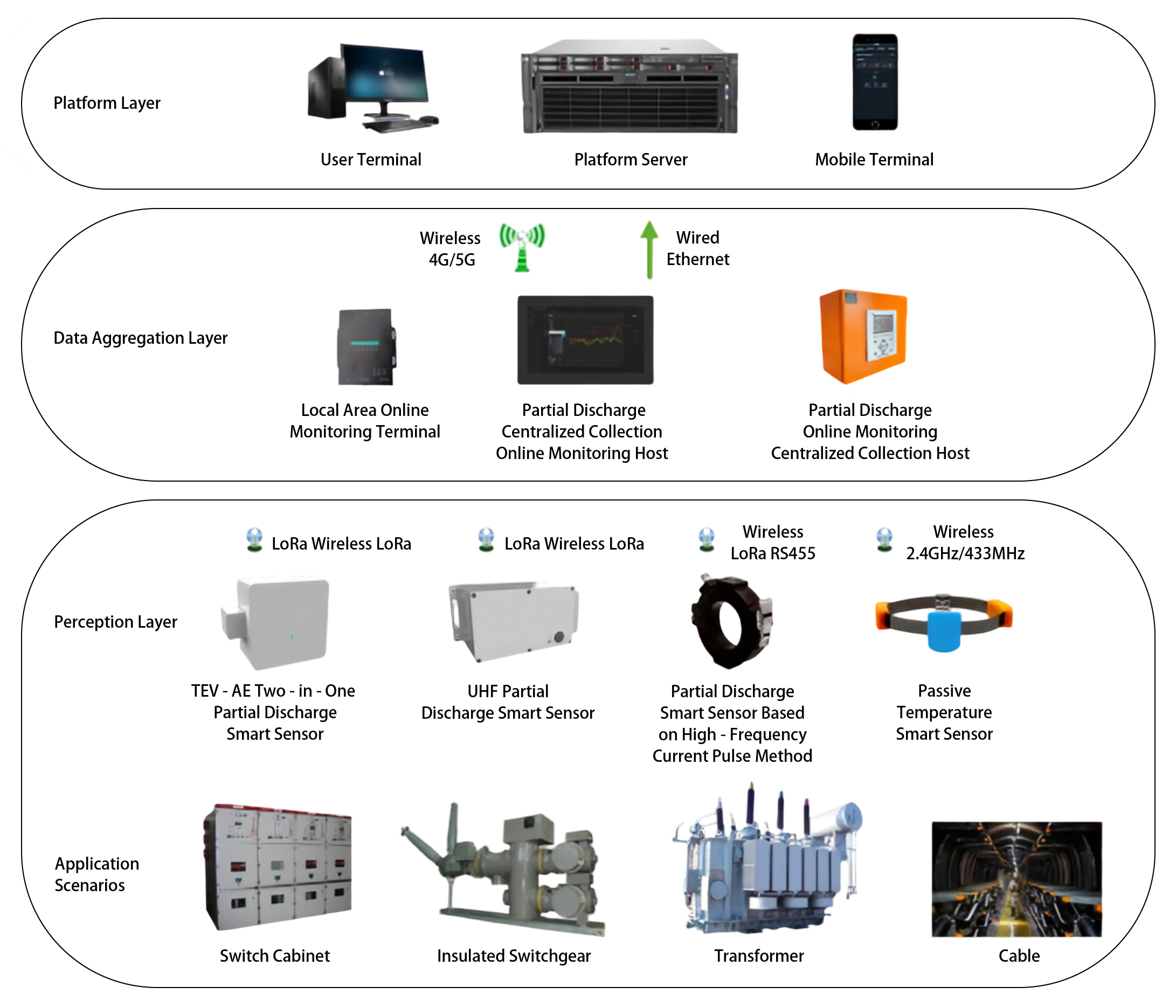
GOWE-9000 Partial discharge online monitoring system
detail
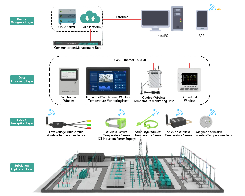
GOWE-9000 Wireless Temperature Monitoring System for Substations
detail
GWZC-9604 Feeder Arc Flash Protection Relay
detail
Technical More
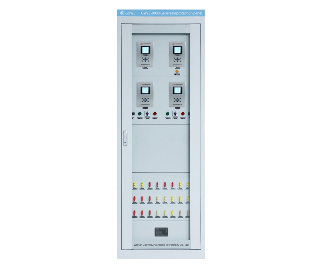
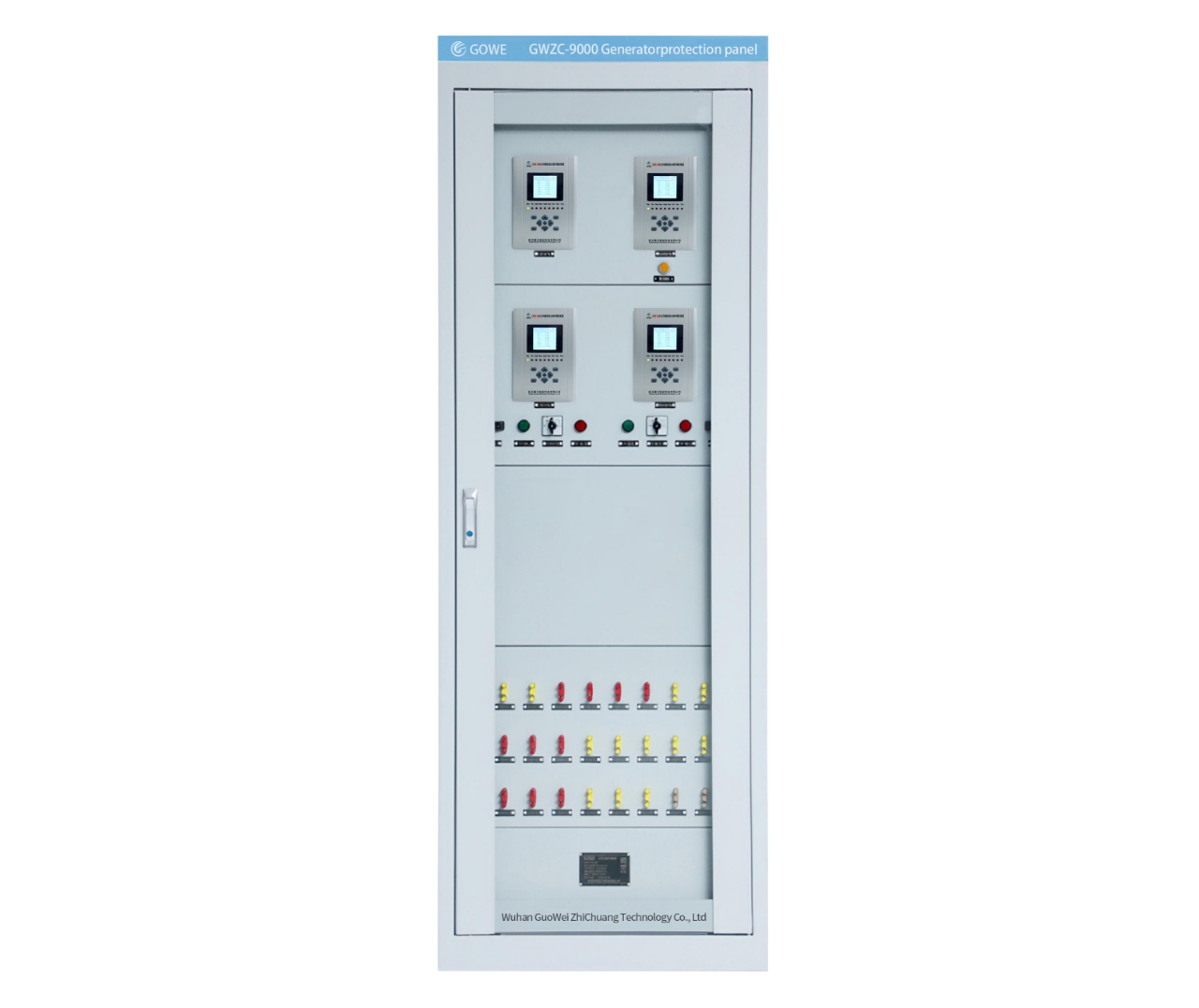
Generator Protection Panel
Generator Protection Relay Panel : Composition and Function
Integrating protection, measurement, and communication, the Generator Protection Relay Panel can realize the protection and control of various units, enabling unattended or minimally attended operation. It can achieve generator differential protection, rotor earth fault protection, stator earth fault protection, excitation protection, overcurrent protection, overvoltage protection, overload protection, backup protection, etc.
2025/11/25
Main Transformer-Protection Panel
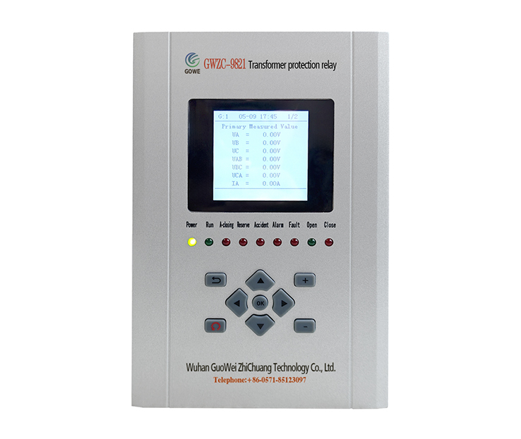
Transformer Protection Relay Panel:Composition and Function
Transformer Protection Relay Panel is primarily used in automation systems for substations and distribution stations in power systems of 11kV, 33kV, 132kV and above. Its main function is to ensure that the transformer can promptly trip the faulty circuit in case of overload, short circuit, gas relay activation, and other abnormal operating conditions, thereby protecting the main transformer from damage and preventing the expansion of faults.
2025/11/24
Feeder Protection Relay
Common Protection Functions for Feeder Protection Relays?
Feeder protection relays are a type of line protection relay and serve as critical devices in distribution systems for protecting power cables (feeders). They integrate multiple protection functions to achieve comprehensive, reliable, and selective protection. Below are the commonly used protection functions of feeder protection relays, along with their corresponding ANSI codes.
2025/11/14
Transformer protection relay
Transformer Differential Protection(ANSI 87T): Working Principle, Function, and Setting Calculation
The working principle of the Transformer Differential Protection Relay is based on Kirchhoff's Current Law. This law states that the sum of currents entering a node is zero. Ideally, for a healthy (non-faulted) transformer, the current entering the primary winding should equal the current leaving the secondary winding (after accounting for the transformer's turns ratio and phase shift).
2025/11/12
Inquiry Consultation
+86-17621210051
+86-17621210051
+86-17621210051
+86-17621210051
home product email
live chat
my