1. System Overview
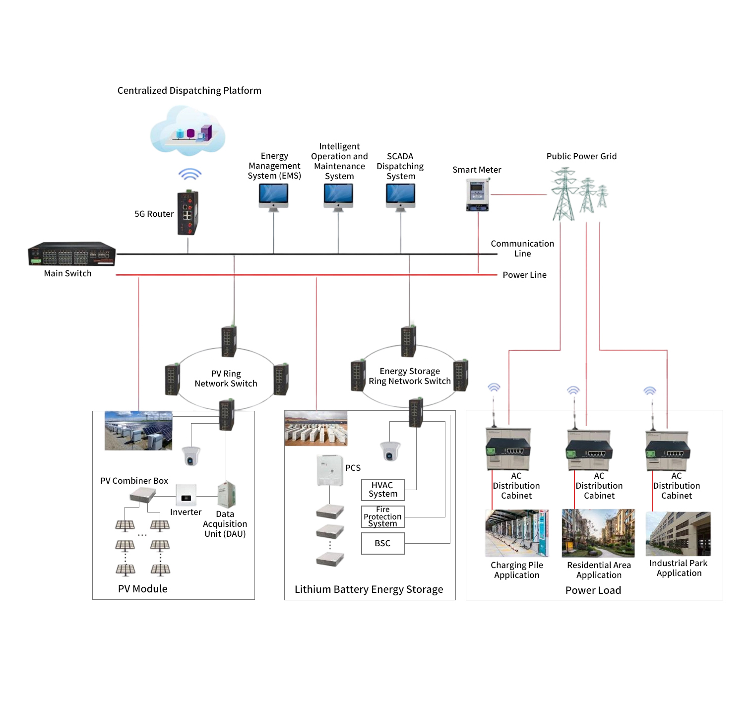
The waste-to-energy power plant automation system serves as the core control platform for modern waste treatment facilities. By integrating advanced computer technology, network communication technology, and automatic control technology, it achieves comprehensive monitoring and optimized management of the incineration process. Designed with a “centralized management, distributed control” principle, the system implements automated operation of all plant equipment through a multi-level network architecture, ensuring stable incineration processes, compliance with environmental standards, and efficient energy recovery.
 The system features real-time data acquisition, process control, safety interlocking, energy efficiency analysis, and environmental monitoring. It significantly improves waste treatment efficiency, reduces operational costs, and meets stringent emission standards.
2. System Composition
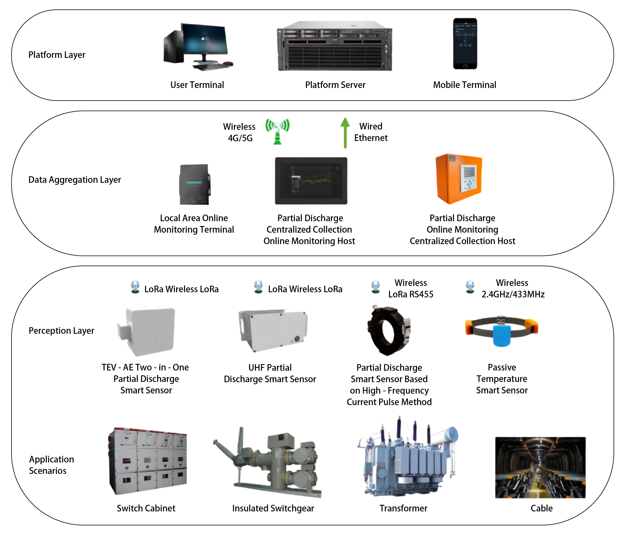
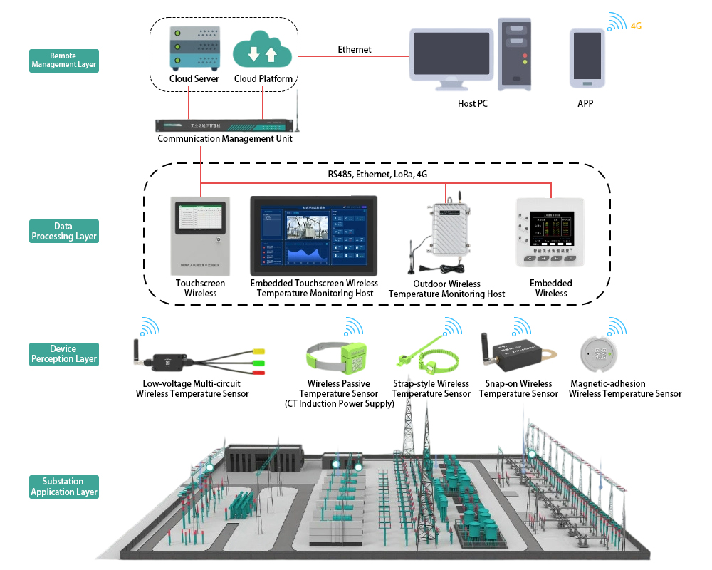
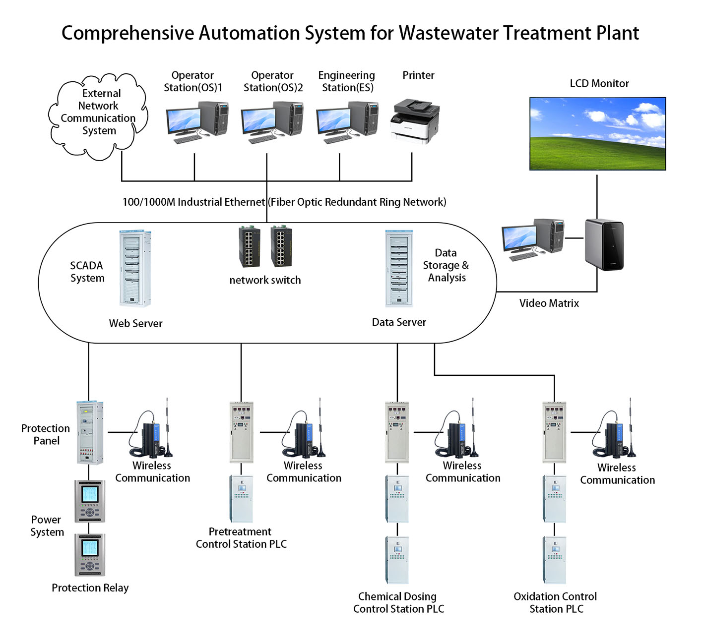
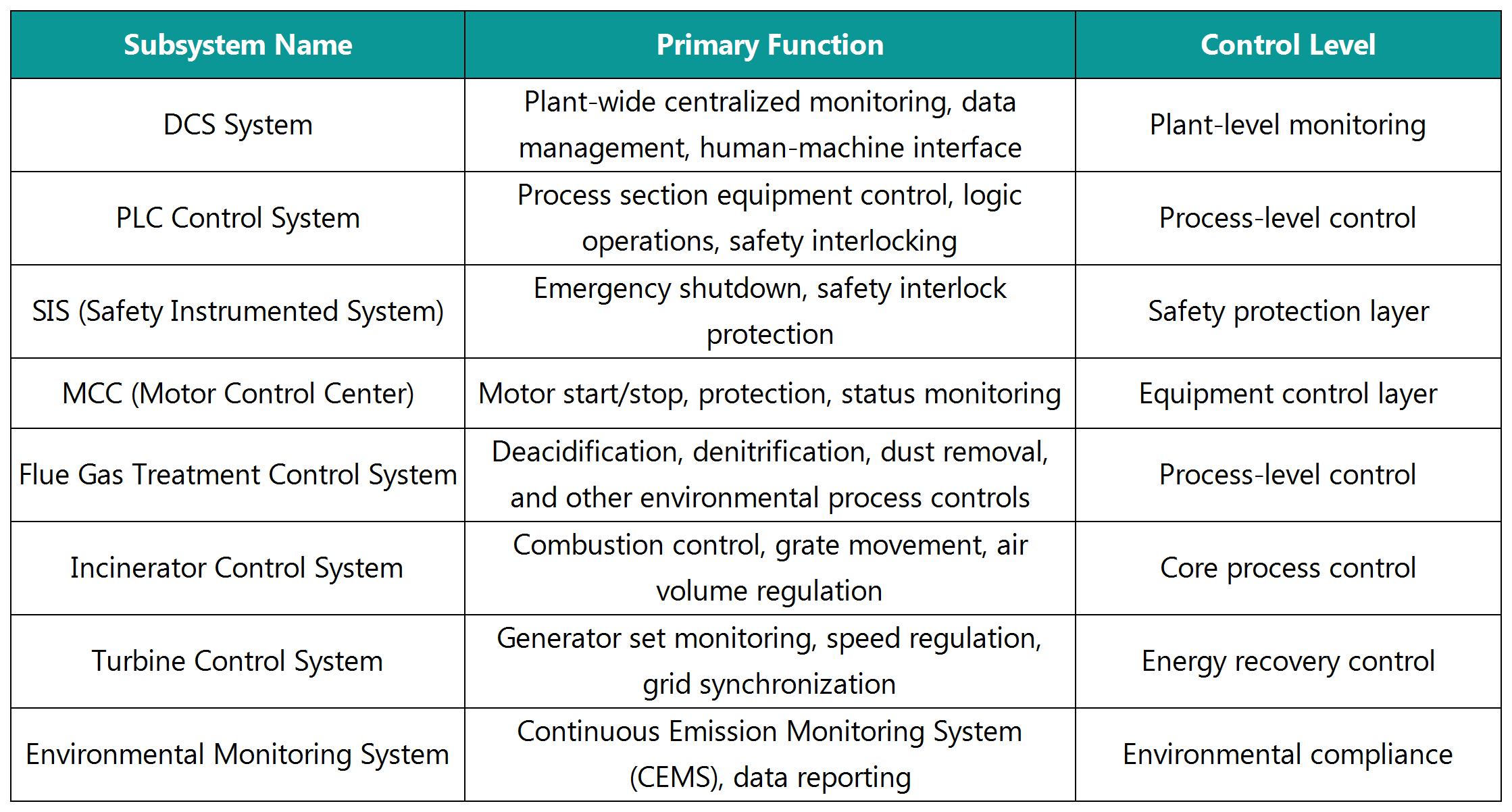
2.1 Main Subsystem Architecture
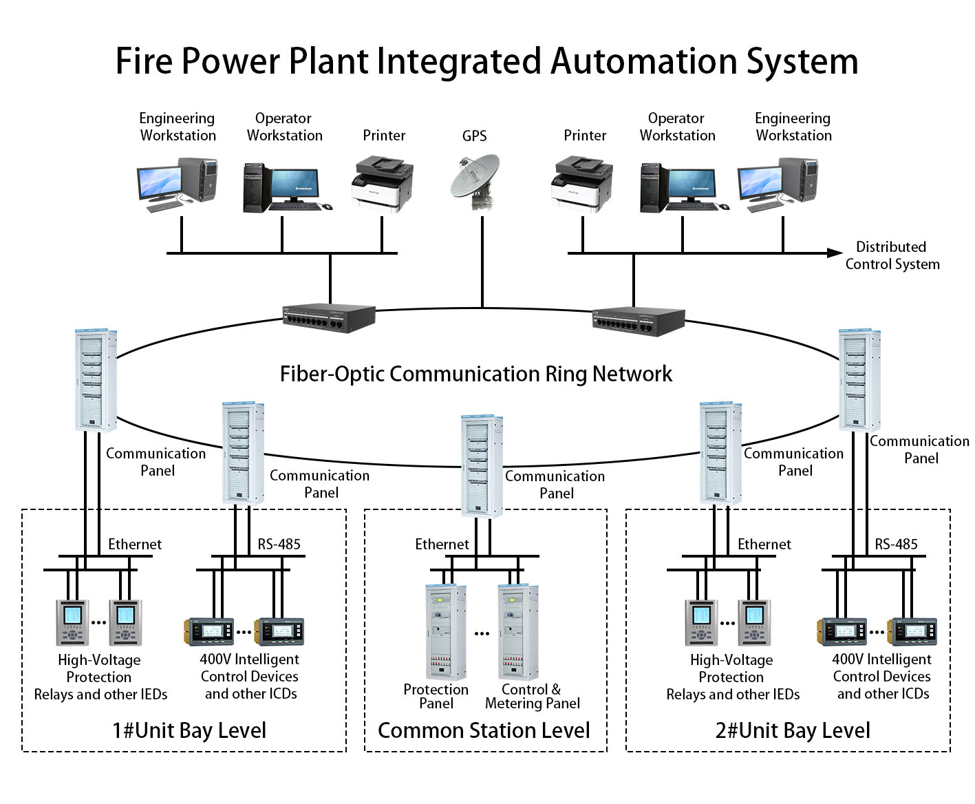
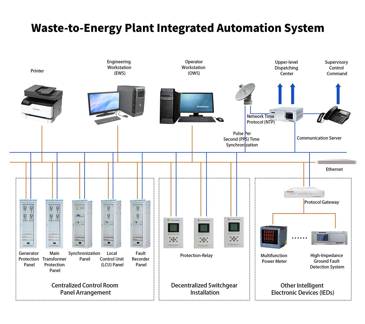
2.2 Network Communication Architecture
Upper-Level Network: Industrial Ethernet (100/1000 Mbps) for high-speed data exchange between DCS operator stations, engineering stations, and servers, supporting OPC, Modbus TCP, and other standard protocols.
Control-Level Network: Redundant PROFIBUS-DP or Modbus RTU fieldbus for reliable real-time data transmission between PLCs and remote I/O stations, smart instruments, etc.
Device-Level Network: Hardwired connections or DeviceNet fieldbus for actuators, sensors, and other terminal devices.
3. System Hardware and Software Configuration
3.1 Hardware Configuration
DCS System Hardware:
Servers: Redundant industrial-grade servers with dual power supplies and RAID5 disk arrays
Operator Stations: Dustproof and corrosion-resistant industrial PCs (21-24″ touchscreen)
Network Equipment: Industrial-grade switches, fiber optic transceivers, redundant network architecture
Controllers: Multi-loop process controllers
PLC Control System:
Main Controllers: Large/medium-sized programmable controllers (for incinerator control), small/medium-sized programmable controllers (for auxiliary systems)
Remote I/O Stations: Distributed I/O modules with IP65 protection rating
Special Modules: High-speed counter modules (for grate movement control), RTD/thermocouple input modules
Redundancy: CPU redundancy, power redundancy, and communication redundancy for critical process sections
Protection and Safety Equipment:
Generator Protection Relays:Differential Protection (ANSI 87G).Stator Ground Fault Protection (ANSI 64G/59N).Loss of Excitation Protection (ANSI 40).Overcurrent Protection (ANSI 51V/50).Negative Sequence Overcurrent Protection (ANSI 46).Overvoltage Protection (ANSI 59).Reverse Power Protection (ANSI 32).Underfrequency Protection (ANSI 81U).Overfrequency Protection (ANSI 81O)
Motor Protection Relays:Overload Protection (ANSI 49/51).Short Circuit Protection (ANSI 50).Ground Fault Protection (ANSI 50G/51G).Phase Unbalance Protection (ANSI 46).Locked Rotor Protection (ANSI 48/51LR)
Transformer Protection Relays:Differential Protection (ANSI 87T).Buchholz/Gas Detection Protection (ANSI 63).Overcurrent Protection (ANSI 50/51).Zero Sequence Overcurrent Protection (ANSI 51N).Overload Protection (ANSI 49).Oil Temperature Protection (ANSI 26).Oil Level Protection (ANSI 71).Pressure Relief Protection (ANSI 63PR)
Line Protection Relays:Distance Protection (ANSI 21).Overcurrent Protection (ANSI 50/51).Overvoltage Protection (ANSI 59).Zero Sequence Current Protection (ANSI 51N/67N).Auto-Reclosing (ANSI 79).High Frequency Protection (ANSI 81H).Directional Protection (ANSI 32/67)
Non-Electrical Protection Relays: Gas protection, temperature protection, pressure protection, and other mechanical protection functions
Safety Relays: Compliant with IEC 61508, SIL3 safety level, force-guided contact structure
UPS: Online double-conversion UPS with ≥2 hours backup time
Field Instruments:
Temperature: Wear-resistant thermocouples (incinerator), infrared pyrometers (grate)
Pressure: Smart pressure transmitters
Flow: Electromagnetic flowmeters (liquids), vortex flowmeters (steam)
Level: Radar level transmitters (waste pit), ultrasonic level transmitters (lime silo)
Gas Analysis: Infrared gas analyzers (flue gas composition), laser gas analyzers
3.2 Software Configuration
Supervisory Layer Software:
SCADA Platform: IEC 61131-3 compliant SCADA system
Database: Real-time database, relational database
Advanced Applications: Incineration optimization software, intelligent control algorithms
Reporting Tools: Standardized reporting system
Control Layer Software:
PLC Programming Software: IEC 61131-3 compliant programming environment
Configuration Tools: Standardized configuration software
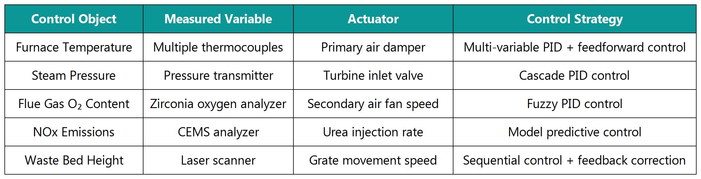
Control Algorithms: PID control blocks, fuzzy logic modules, sequential control function blocks
Specialized Software Packages:
Incinerator Control Software: Grate control algorithms, combustion models
Flue Gas Treatment Optimization: Deacidification control strategies, denitrification optimization
Predictive Maintenance System: Equipment health monitoring
Through rigorous hierarchical design and redundant configurations, the system ensures stable and reliable incineration processes with emissions performance exceeding national standards. Typical automation availability reaches ≥98%, with thermal efficiency improvements of 15-20%, significantly enhancing the plant’s economic and environmental benefits.