I. Solution Overview
With the global energy structure accelerating its transformation towards sustainability, small and medium-sized hydropower stations have become an important part of the power supply system due to their wide geographical distribution, short construction cycle, and low environmental impact. However, currently, a large number of small and medium-sized hydropower stations are facing issues such as aging equipment, lagging automation levels, and high operation and maintenance costs. These problems severely restrict the economic benefits of the stations and pose challenges to the stability of power supply.
This comprehensive automation system solution utilizes cutting-edge computer technology, communication technology, and automation control technology to achieve intelligent monitoring and management of the entire production and operation process of small and medium-sized hydropower stations. By building an integrated automation system, it conducts centralized control over primary equipment such as generator sets, high and low voltage switchgear, and transformers, as well as secondary equipment such as relay protection, communication, and synchronization systems. This enables real-time data collection and accurate transmission, remote operation and intelligent adjustment of equipment, and rapid diagnosis and processing of faults, comprehensively improving the automation level, operation efficiency, and reliability of hydropower stations, and promoting their upgrade towards intelligent, efficient, and unattended or minimally attended operation modes.
 II. Design Standards
1.Electrical Standards: Strictly comply with the IEC 60255 series of standards to ensure the precise and reliable operation of relay protection and safety automatic devices, enabling a rapid response to various faults and abnormal working conditions and safeguarding the safety of electrical equipment. Design the station service power system in accordance with IEEE 1100 IEEE Recommended Practice for Powering and Grounding Electronic Equipment to ensure stable supply of station service power and meet the power demand of station equipment.
2.Automation Standards: Refer to IEC 61850 Power utility automation – Communication networks and systems for power utility automation to construct a computer monitoring system for real-time monitoring and control of the operation status of hydropower stations. Comply with standards such as ISO 9241 – 11 Ergonomic requirements for office work with visual display terminals (VDTs) – Part 11: Guidance on usability to ensure the usability and operational rationality of the system’s human-machine interface. Conduct strict international acceptance processes to ensure that the system performance meets the standards.
3.Communication Standards: Adopt the IEC 60870 – 5 series of communication protocols, including IEC 60870 – 5 – 101 and IEC 60870 – 5 – 104, to achieve efficient and stable communication with superior dispatching centers and intelligent devices. Meanwhile, be compatible with internationally common communication protocols such as Modbus TCP and DNP3 to enhance the communication compatibility of the system.
4.Environmental Standards: System equipment shall meet the IEC 60068 series of environmental test standards, covering tests for temperature, humidity, vibration, shock, etc., to ensure stable operation in complex and harsh environments. At the same time, comply with safety standards such as UL 508 Standard for Industrial Control Equipment to ensure the safe use of equipment.
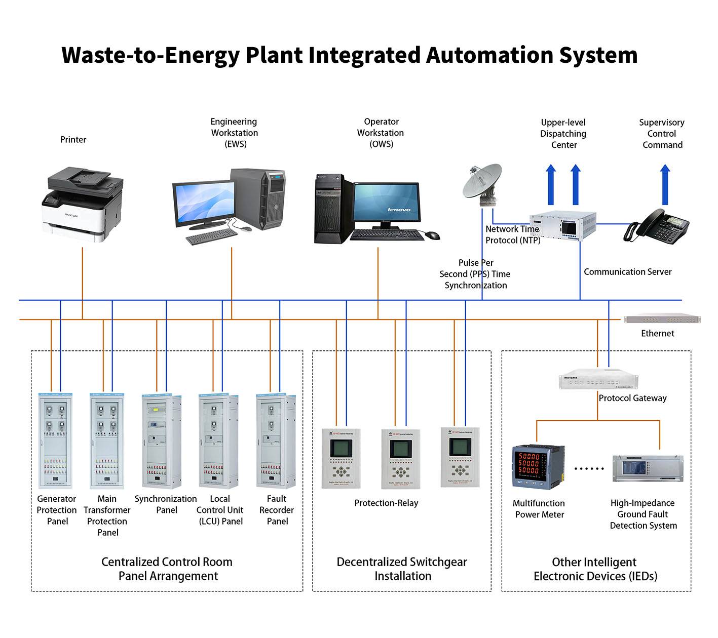
III. System Composition
(I) Primary System
1.Generator Sets: Comprise turbines, generators, and supporting equipment. Turbine selection is based on the IEC 60041 Hydraulic turbines – Acceptance tests standard, optimizing the energy conversion efficiency according to parameters such as water head and flow rate. Generators mostly use three-phase AC synchronous generators. According to the capacity and voltage level of the station, determine key parameters such as rated power, rated voltage, and rated current with reference to IEEE Std 115 IEEE Guide for Testing Synchronous Machines. Equipped with advanced speed governors and excitation systems, the speed governor precisely adjusts the turbine guide vane opening according to load changes to maintain the stable speed of the unit; the excitation system automatically adjusts the excitation current to ensure the stable terminal voltage of the generator and enhance the stability of the power system.
2.High and Low Voltage Switchgear: High voltage switchgear is used for the control, protection, and monitoring of high voltage circuits. Common types include metal-clad withdrawable switchgear (complying with the IEC 62271 – 200 standard). It is internally equipped with vacuum circuit breakers, isolating switches, current transformers, voltage transformers, surge arresters, and other equipment, and has a complete “five-prevention” function to ensure operational safety. Low voltage switchgear adopts modular designs complying with the IEC 61439 – 2 standard (such as MNS, GCS series, etc.), integrating air circuit breakers, contactors, thermal relays, fuses, and other components to achieve precise control and protection of different loads.
3.Transformers: Include main transformers and station service transformers. The main transformer steps up the output voltage of the generator to a level suitable for grid transmission. The selection is based on the IEC 60076 Power transformers standard, choosing oil-immersed or dry-type transformers according to the station capacity, voltage level, and transmission distance. The station service transformer provides stable low-voltage power for the internal equipment of the station, ensuring the normal operation of station-internal equipment.
4.Transmission Lines and Other Equipment: Transmission lines are responsible for transmitting the electrical energy generated by the station to the power grid. According to the transmission capacity and distance, select appropriate conductor types and voltage levels with reference to IEEE Std 141 IEEE Recommended Practice for Electric Power Distribution for Industrial Plants, and take measures such as lightning protection and anti-pollution flashover to ensure the safety of power transmission. The primary system also includes busbars, isolating switches, grounding switches, current transformers, voltage transformers, surge arresters, and other equipment, which work together to complete the transmission and distribution of electrical energy.
(II) Secondary System
1).Relay Protection System:
Generator Protection: Configure differential protection (complying with the IEEE C37.110 standard) to quickly cut off internal phase-to-phase short-circuit faults of the generator; overcurrent protection and overvoltage protection to prevent external short circuits and abnormal voltages; loss-of-excitation protection (based on the IEEE Std 125 standard) to monitor the loss-of-excitation status of the generator; also set up rotor grounding protection, stator winding turn-to-turn short-circuit protection, etc., to comprehensively safeguard the safety of the generator.
Transformer Protection: Set differential protection (complying with the IEC 60289 standard) as the main protection for internal winding and outgoing line faults; gas protection to monitor internal faults of the transformer and changes in oil level; combined with overcurrent protection, overloading protection, zero-sequence protection, etc., to achieve comprehensive protection of the transformer.
Line Protection: Adopt overcurrent protection, zero-sequence protection, distance protection (referring to the IEEE C37.113 standard), and reasonably configure them according to the voltage level, length, and operation mode of the line to quickly cut off line faults and ensure the stability of the power grid.
2).Communication System:
Intra-station Communication: Take industrial Ethernet as the core, and comply with the IEEE 802.3 standard to achieve high-speed data transmission between the monitoring system and local control units, protection devices, and other equipment. Supplemented by fieldbuses (such as PROFIBUS – DP, Modbus RTU) to connect remote or equipment with high real-time requirements, constructing a multi-level intra-station communication network.
Remote Communication: Through means such as optical fiber, microwave, and power line carrier, communicate with superior dispatching centers in accordance with the ITU – T series of standards, uploading real-time operation data of the station and receiving control commands. Use wireless communication technologies such as 4G/5G as backup solutions to improve the reliability and flexibility of communication.
3).Synchronization System:
During the generator grid connection process, the synchronization system monitors in real-time the voltage, frequency, and phase parameters of the generator and the power grid (complying with the IEEE Std 100 standard). By automatically adjusting the speed and excitation current of the generator, it ensures that the parameters of both match, achieving safe grid connection. The system consists of a synchronization device, voltage transformers, current transformers, synchronization switches, etc., and supports both manual and automatic synchronization operation modes.
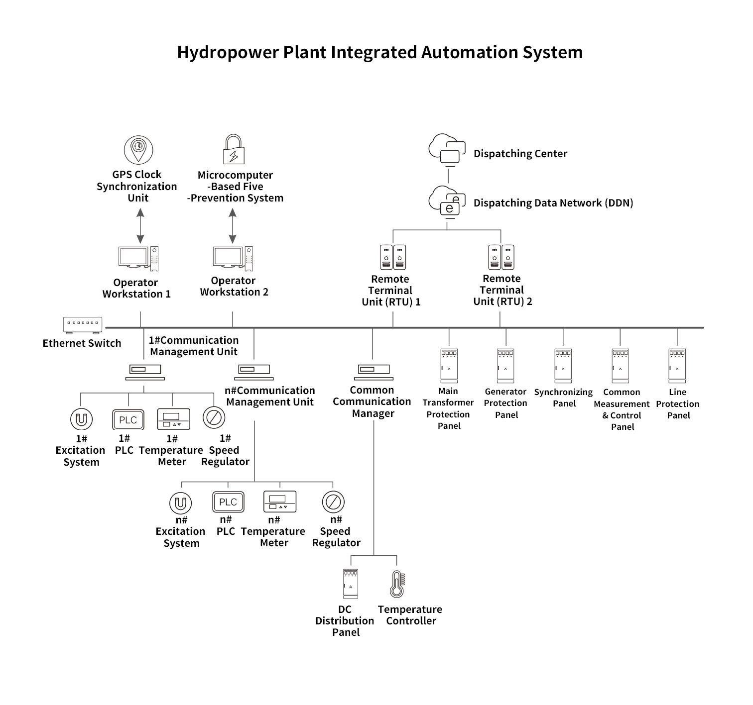
4).Monitoring System:
Station Control Layer: Composed of operator workstations, engineer workstations, and servers. The operator workstation is designed based on ergonomics, providing an intuitive operation interface for monitoring the operation of the station and controlling equipment; the engineer workstation is used for system maintenance and parameter setting; the server conducts data storage and management in accordance with the ISO 27001 standard to ensure the security and reliability of real-time data, historical data, and event records.
Local Control Layer: Includes local control units (LCUs) for generator sets and switchyards. Use PLCs or industrial control computers (complying with the IEC 61131 – 2 standard) as core controllers. The LCU for generator sets real-time monitors and controls the generator sets and their auxiliary equipment, collects operation parameters, and controls the start/stop, mode conversion, and load regulation; the local control unit for the switchyard realizes the monitoring, protection, and switching control of high and low voltage switchgear, transformers, and other equipment.
5.DC System:
Provides a stable DC power supply for secondary equipment to ensure the normal operation of the system in case of AC power failure. The system consists of a charging device, a battery bank, and a DC feeder panel. The charging device converts AC power into DC power and manages the charging and discharging of the battery bank. The battery bank serves as a backup power source, and the DC feeder panel is responsible for power distribution to meet the power demand of secondary equipment.
6.Automatic Devices:
Automatic Synchronizing Device: Based on the IEEE Std 100 standard, it automatically detects the synchronization conditions during the generator grid connection process, adjusts the speed and excitation current, and achieves fast and accurate grid connection, improving the grid connection efficiency and reliability.
Automatic Voltage Regulator (AVR): Integrated into the generator excitation system, it automatically adjusts the excitation current according to the change in the generator terminal voltage to maintain voltage stability, meeting the requirements of the IEEE Std 421.5 standard.
Automatic Generation Control (AGC): Receives load commands from the grid dispatching center and automatically adjusts the active power output of the units, following the IEEE Std 122 standard to achieve automatic load distribution and frequency stability of the power grid.
Automatic Standby Power Switching Device (BZT): When the working power fails, it automatically switches to the standby power source to ensure the continuous power supply of important equipment and improve the reliability of power supply.
IV. Summary of Key Points
1. System Integration: The system integrates primary and secondary equipment and multiple subsystems. By adopting internationally common communication protocols (such as IEC 61850, Modbus TCP) and standardized interface designs, it ensures seamless docking of all equipment and subsystems, enabling efficient data transmission and coordinated operation, and giving full play to the overall effectiveness of the system.
2.Reliability Design: Aiming at the complex operating environment of hydropower stations, improve the system reliability from multiple aspects such as hardware selection (selecting industrial-grade equipment with international certifications), redundant configurations (dual-power supplies, dual-servers, dual-network architectures), and anti-interference measures (complying with the IEC 61000 series of electromagnetic compatibility standards), ensuring the stable operation of the system under harsh conditions.
3.Intelligent Functions: Introduce AI and big data technologies to achieve intelligent data collection and analysis, fault diagnosis and early warning, and intelligent equipment control. Through in-depth mining of operation data, potential equipment faults can be predicted in advance; the operation parameters of the units can be automatically optimized according to the grid load and station operation conditions, improving power generation efficiency and economic benefits.
4.Maintainability: Adopt a modular design concept, where each functional module operates independently, facilitating fault troubleshooting and replacement. Integrate a complete self-diagnosis function to monitor the system status in real-time and locate faults; provide maintenance tools and interfaces in line with international operating habits, reducing the difficulty of operation and maintenance and improving operation and maintenance efficiency.
5.Scalability: The system architecture is designed in accordance with international open standards, reserving sufficient hardware interfaces and software function expansion spaces, supporting the seamless access of new equipment and new functional modules, meeting the future upgrading and transformation needs of hydropower stations, and realizing the smooth expansion of the system.