


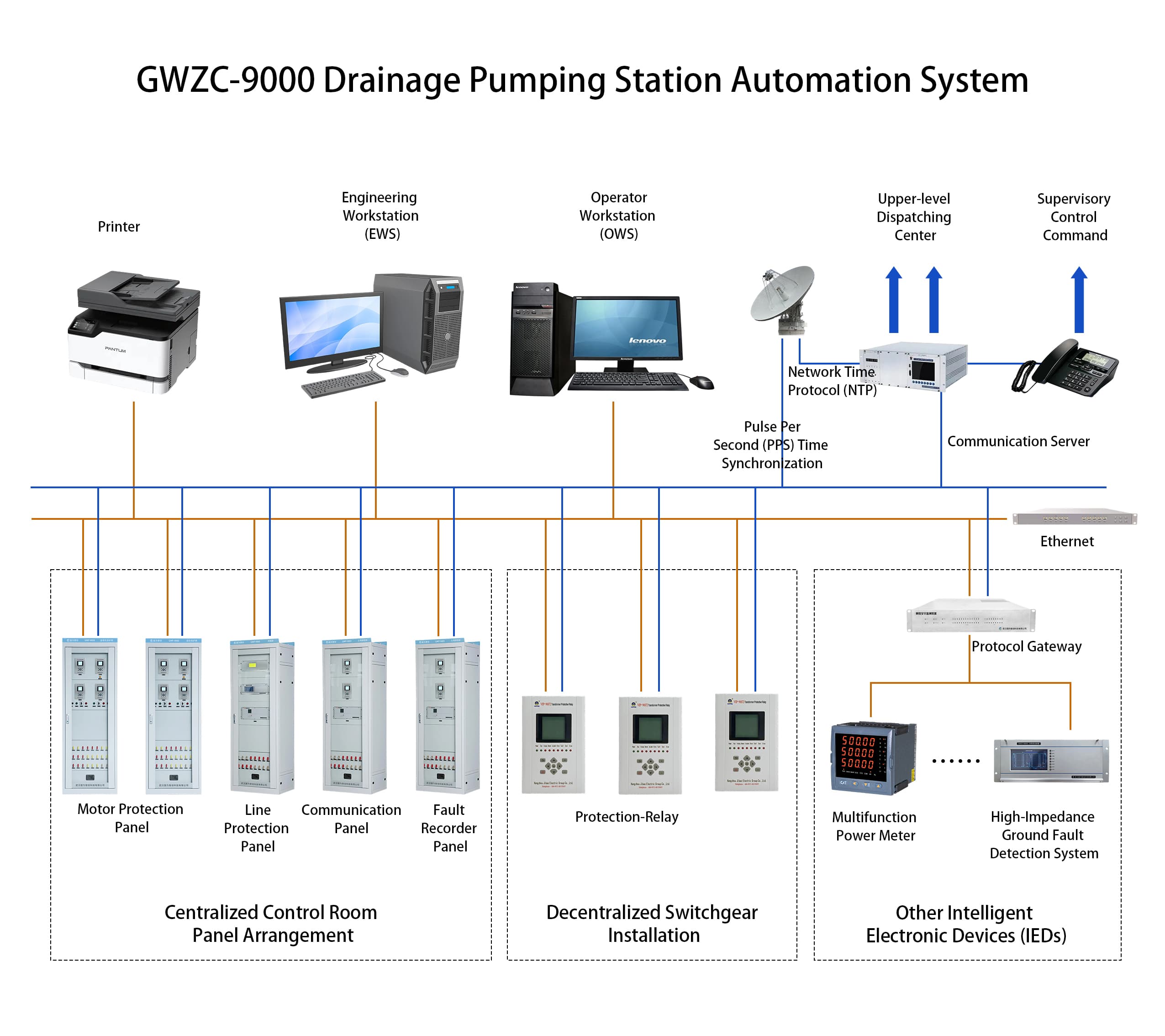
Drainage Pumping Station Automation System—Forging a New Urban Flood Control Ecosystem
Drainage pump stations employ electromechanical systems for active water discharge, IoT and AI for precise regulation, and backup power for reliability. Digital twin platforms optimize decision-making with failure prediction and damage assessment. Each ¥100M investment reduces annual losses by ¥230M while saving 30% energy, as proven by Tokyo's flood defense system.
2025/07/23
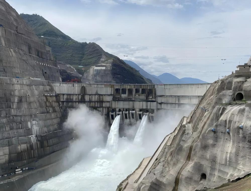
Comprehensive Analysis of the Yarlung Zangbo River Hydropower Station
Massive hydropower potential, extreme seismic/geological challenges, unprecedented engineering (tunnels, dam, turbines), sensitive ecology, and critical transboundary impacts.
2025/07/22

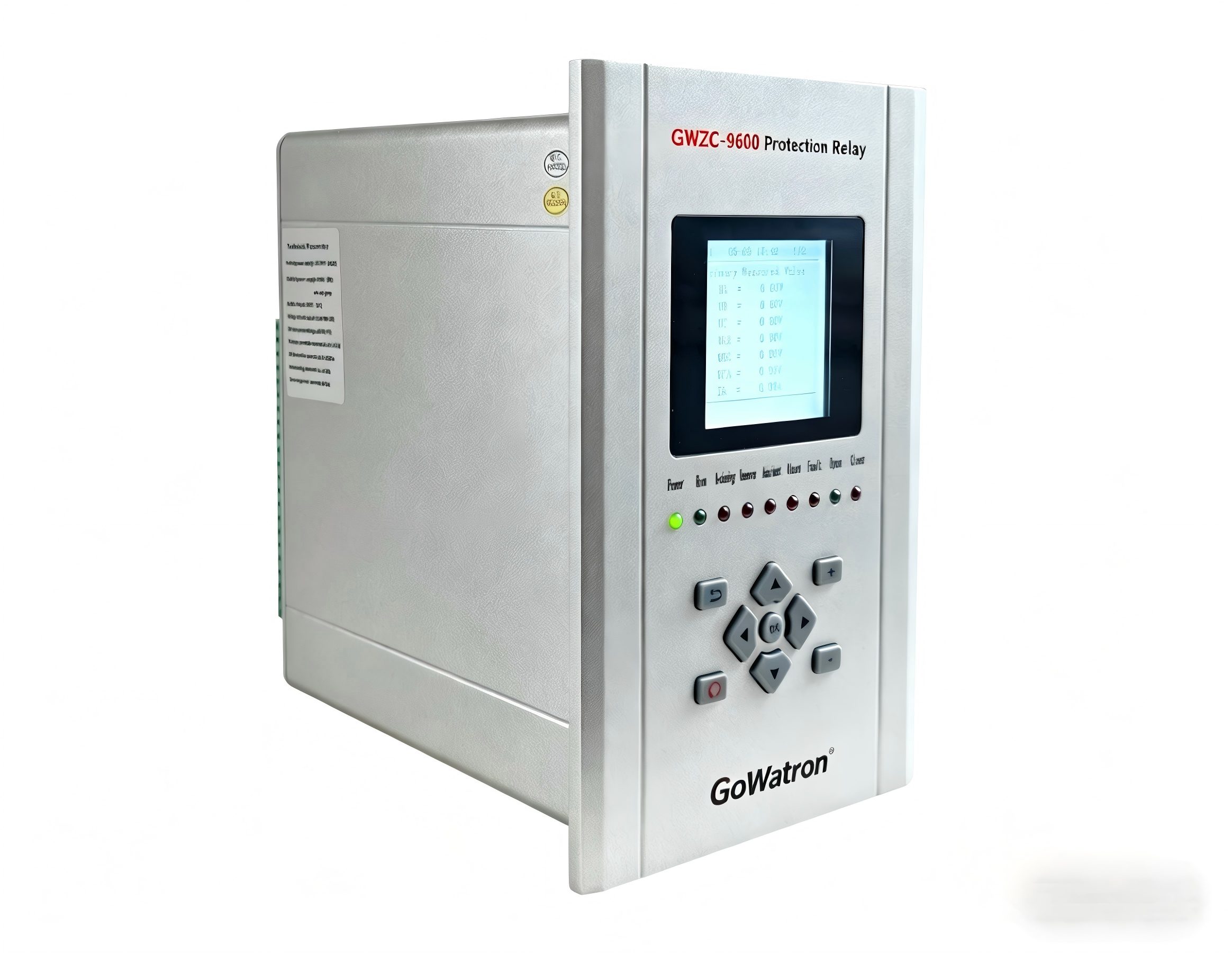
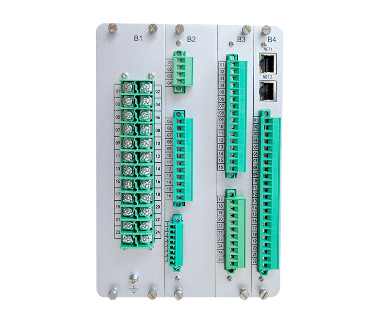
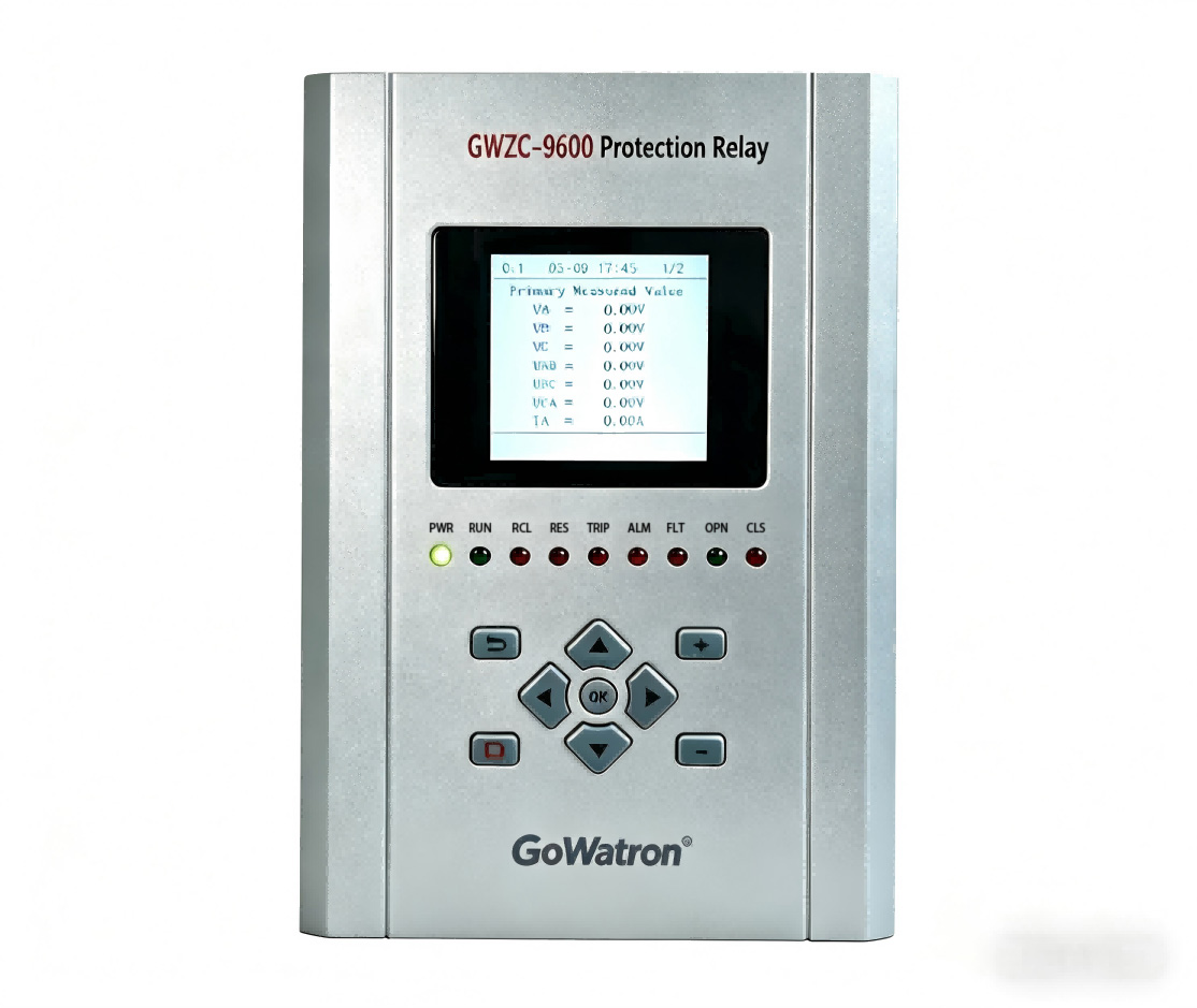
Comprehensive Protection Relay: Full Analysis
A comprehensive protection relay is an intelligent device that safeguards electrical systems by detecting faults (e.g., overcurrent, short circuits) and isolating affected equipment. It integrates multiple protection functions, ensures system reliability, and prevents damage. This guide covers its definition, working principle, protection targets, activation conditions, and outcomes.
2025/07/18


