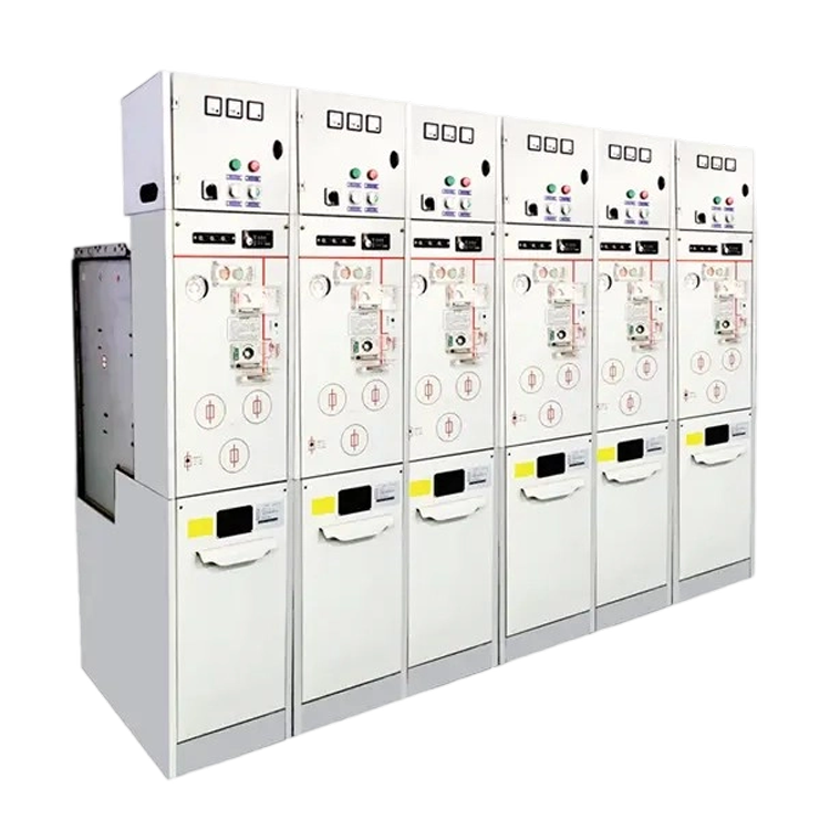


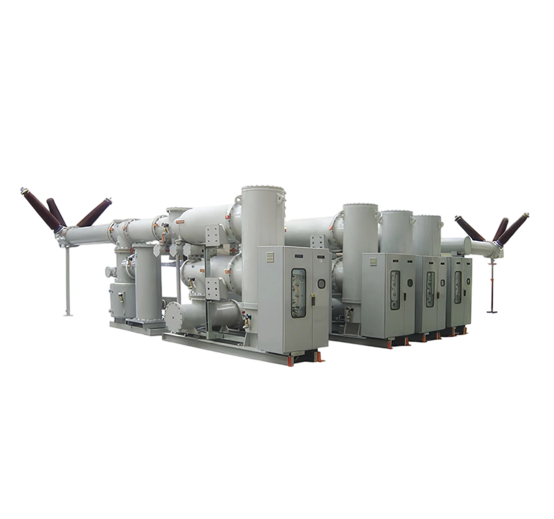
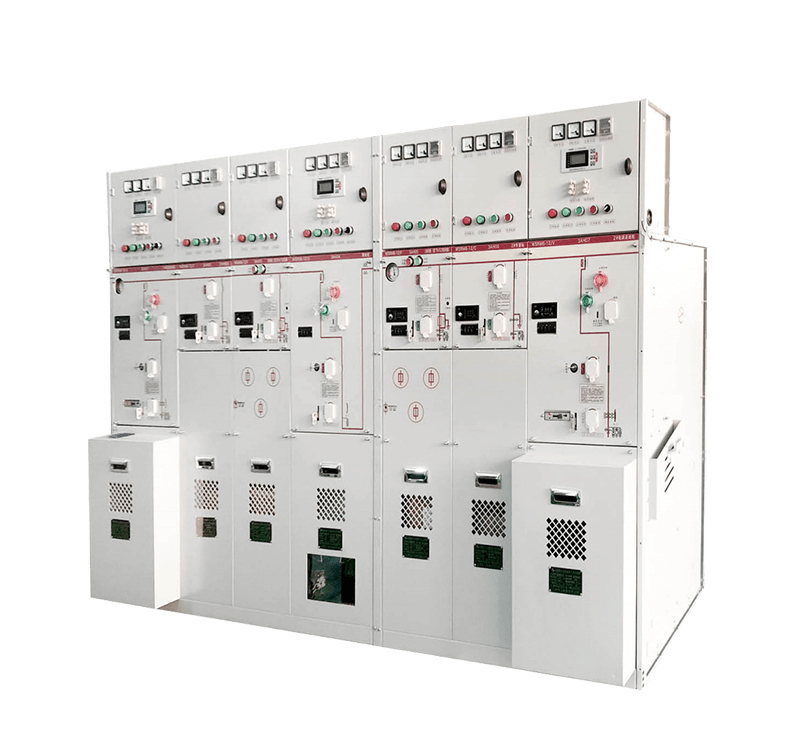
High-voltage electrical equipment carries voltages ranging from several thousand to millions of volts. These high voltages are conducted through busbars, which must be isolated from the ground and supported by non-conductive insulation components. In addition to the normal operating voltage, high-voltage systems are subject to switching overvoltages and lightning impulse overvoltages, which can be 3 to 8 times the operating voltage. Insulation components must therefore withstand both the normal operating voltage and these overvoltage conditions while maintaining insulation integrity.
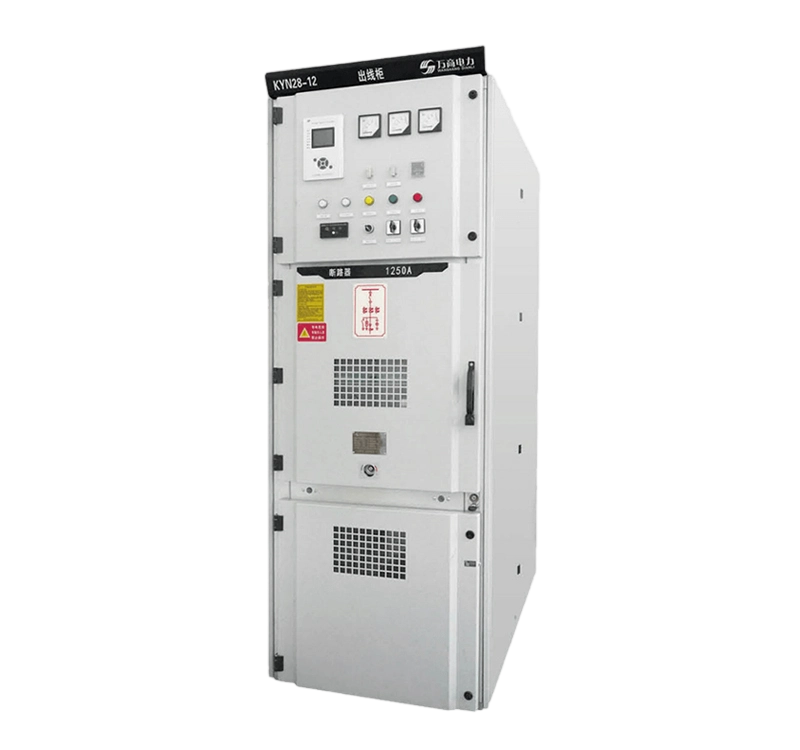
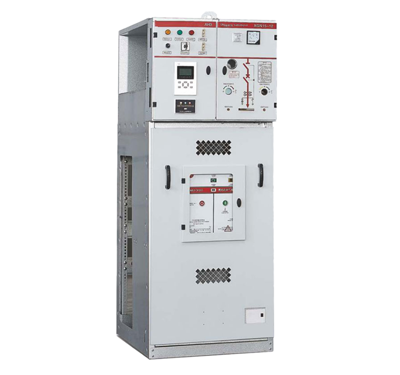
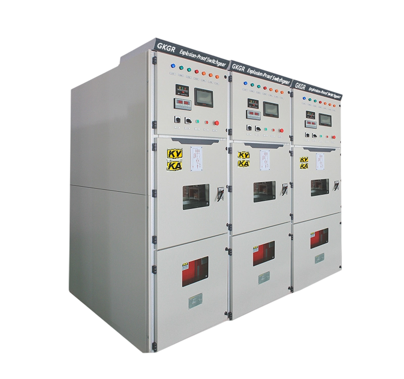
For example, a 12kV medium-voltage switchgear must endure a power-frequency withstand voltage of 42kV and an impulse withstand voltage of 75kV. All insulation components connected between high-voltage and ground or between high-voltage phases must withstand these voltages.
High-voltage switching operations are performed via insulating pull rods to achieve mechanical operation for grounding. Voltage and current are transformed into low-voltage and low-current signals through insulated cast resin electromagnetic induction transformers for use by instruments and Protection Relays.
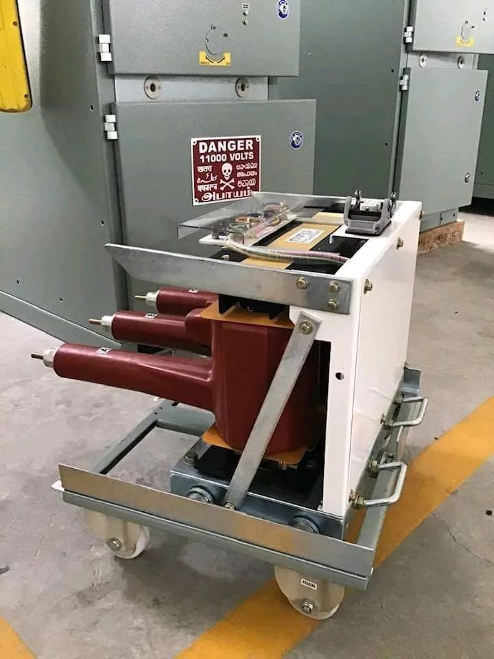
However, some signals cannot be electrically isolated through insulation bodies, such as temperature rise on live high-voltage parts, connection vibrations, and the actual status of busbar switches. Transmitting these signals to the low-voltage side requires isolation, coupling, and other signal transmission methods.
By using temperature sensors directly installed on live high-voltage parts to measure temperature rise, the measured signals can be transmitted wirelessly to receiving devices on the low-voltage side, providing real-time and accurate temperature monitoring.
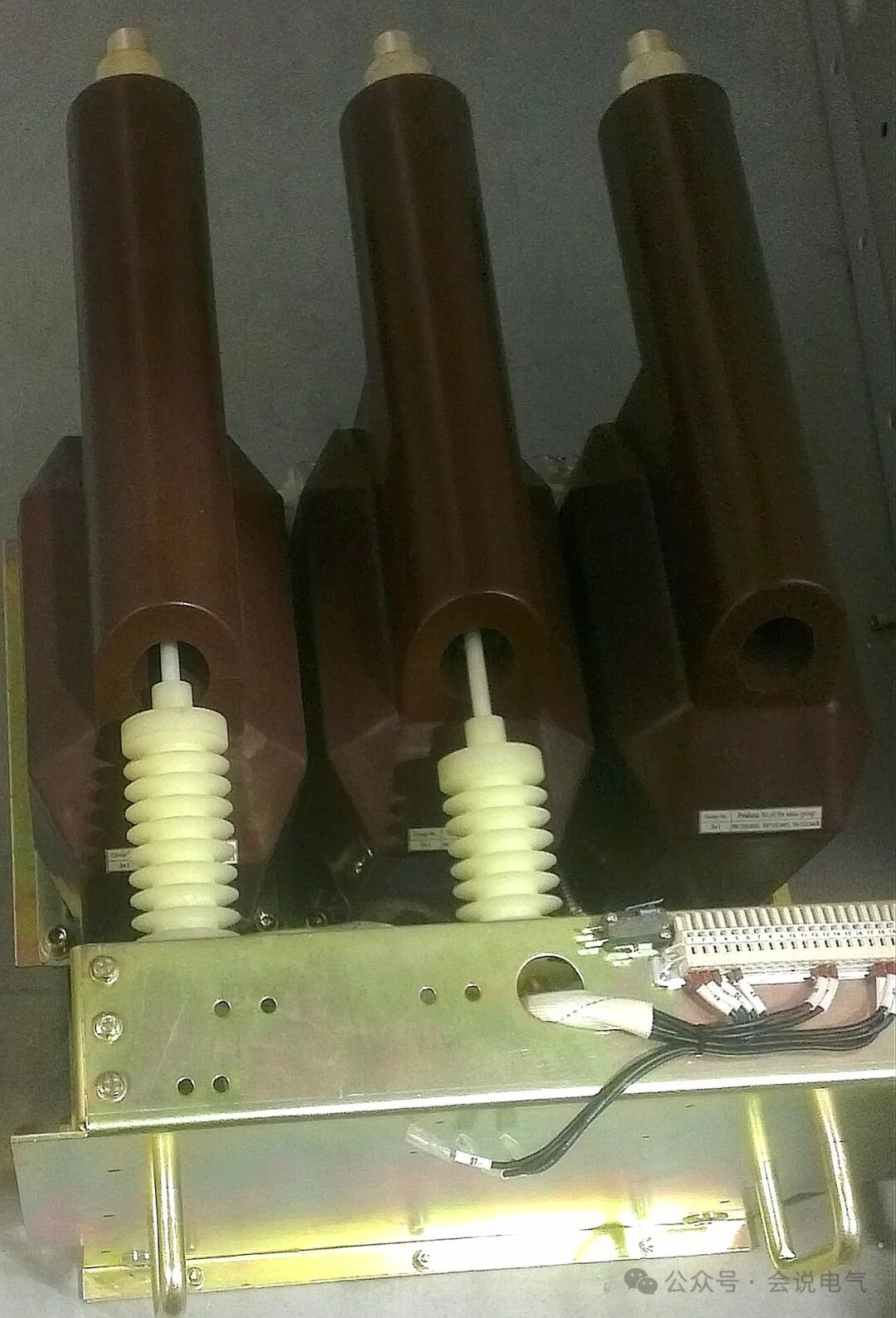
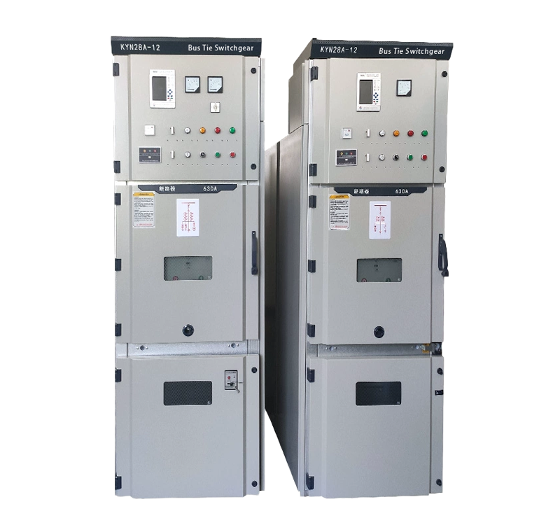
For high-voltage fuse indications, drop-out fuses fall visibly by gravity after melting, allowing clear status identification. However, for microswitch indicators installed inside insulating cylinders, mechanical structures are typically used. To ensure electrical insulation, especially meeting creepage distance requirements, long insulating push rods with skirts are employed for mechanical transmission. When a fuse melts, it drives the push rod to actuate the microswitch, outputting an electrical signal.
Using Near Field Communication (NFC) effectively achieves electrical isolation, enabling one-to-one transmission with high speed and security. This eliminates the need for complex mechanical designs, avoids potential insulation risks, and ensures complete sealing of the fuse insulation cylinder. After a high-voltage fuse melts, the signal is directly transmitted via NFC, and the receiver contactlessly detects the fuse status.
This is particularly critical for 40.5kV fuse indicators, which require a power-frequency withstand voltage of 95kV and a lightning impulse withstand voltage of 185kV. Generally, the creepage distance must be at least 810 mm, and the electrical clearance in air must exceed 300 mm.
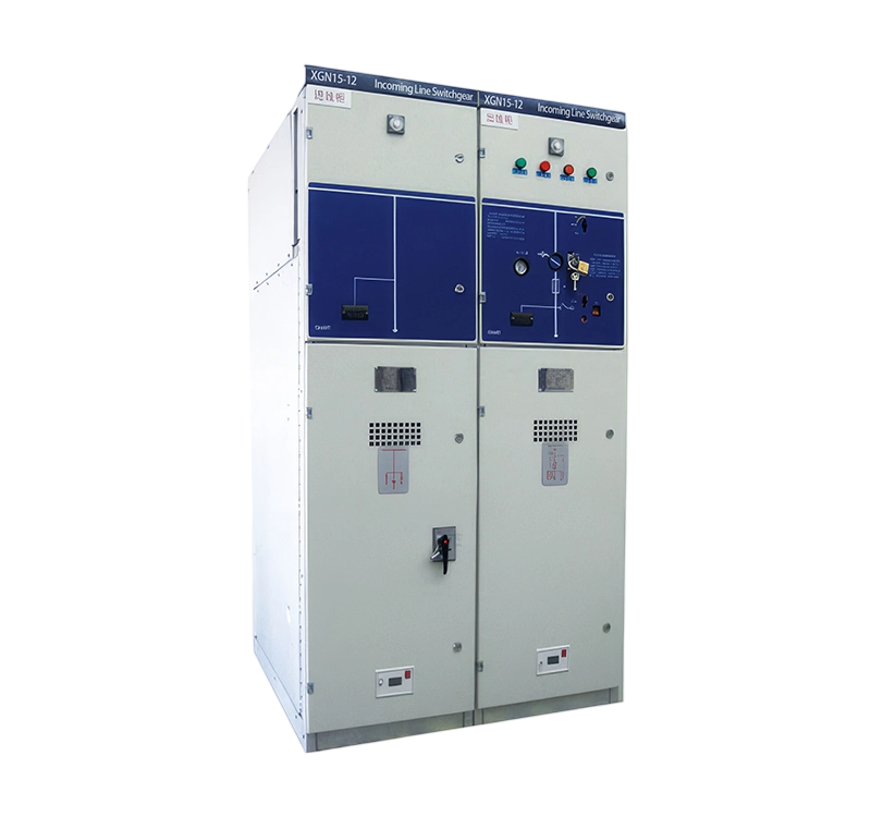
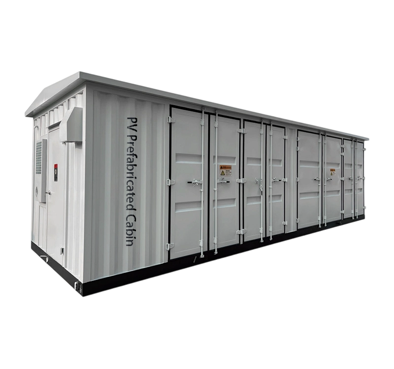
Traditional mechanical drive methods require insulation isolation, long connections, and skirted structures to meet creepage distance requirements. Unlike fully insulated ring main unit fuse cylinders, air-insulated designs cannot achieve complete sealing and thus cannot use silicone rubber for insulation isolation. By adopting wireless communication, the fuse status signal is transmitted via NFC from the high-voltage side, and the receiver installed on the switchgear directly acquires the signal without secondary wiring. This approach eliminates insulation risks and ensures simplicity and reliability.
Additionally, live status detection is achieved through capacitive voltage division via voltage detection sensors. High-voltage sensors detect the voltage, which is transmitted to a voltage indicator to display whether the high-voltage equipment is energized.
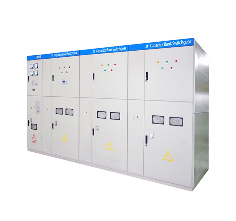
Switchgear may also be equipped with RFID (Radio-Frequency Identification) devices that wirelessly pair with circuit breakers to ensure compatibility in specifications, parameters, and control circuit configurations. This guarantees that the circuit breakers used are fully compatible with the switchgear.


.png)