Substation Wireless Temperature Monitoring System – Product Overview
Substations contain numerous electrical equipment, and manual inspections are inefficient, often missing certain areas and leaving potential safety hazards. The substation environment is harsh, with high voltage, high current, strong magnetic fields, and exposure to outdoor conditions year-round, including rain, snow, and ice, all of which can impact electrical equipment. Compared to other environments, this places higher demands on the quality and data stability of wireless temperature monitoring devices. The primary measurement locations are the surfaces of primary equipment in substations, such as dry-type transformers, box-type transformers, disconnect switches, conductive busbar joints, cable joints, and high-voltage switchgear contacts.
The quality of crimping in electrical equipment joints can only be detected during operation. Over time, these joints are prone to overheating and burnout incidents. A typical 110KV substation has hundreds of cable joints across various monitoring points—some outdoors, some indoors, and some exposed at elevated heights—making conventional wired temperature monitoring methods impractical. Wireless temperature sensors offer easy installation, compact size, and require no modification to existing structures. Each device has a unique address, enabling simple network integration and short installation cycles.
Substation Wireless Temperature Monitoring System – Detailed System Composition
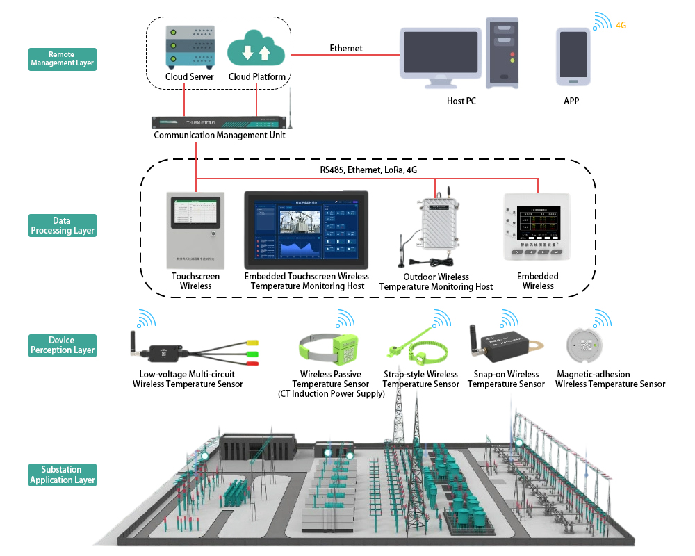
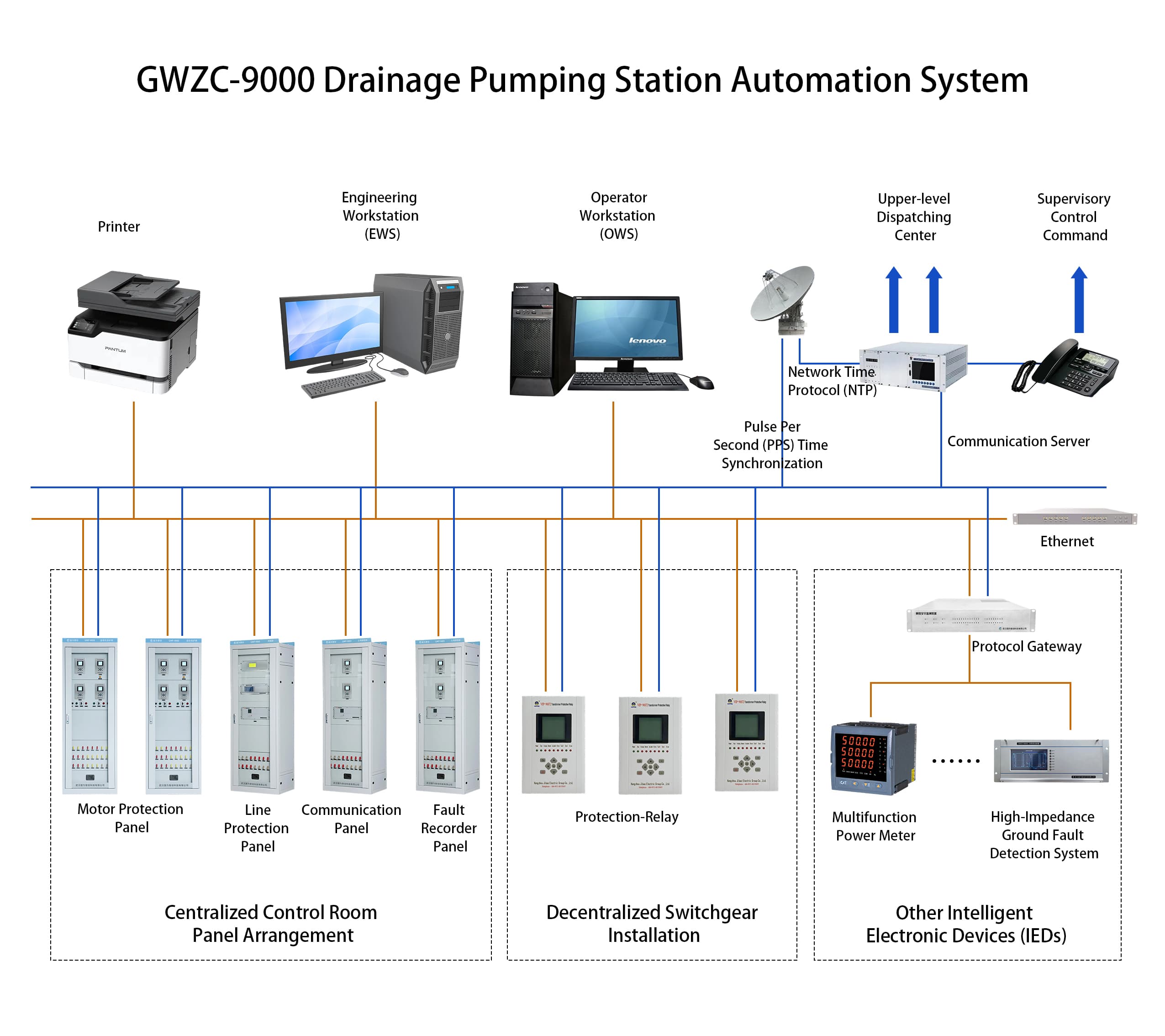
The substation wireless temperature monitoring system typically consists of four components: a wireless temperature monitoring host, wireless temperature sensors, communication modules, and wireless temperature monitoring software. Details are as follows:
- Wireless Temperature Monitoring Host:
Available in two types: touchscreen and standard display screens, selected flexibly based on installation requirements. It primarily displays temperature data from each monitoring point and the overall operational status of the system.
- Communication Module:
Generally categorized into wireless and wired communication. Its main function is to receive data collected by each temperature sensor, aggregate data from all monitoring points, perform analysis and processing, and transmit the data to the wireless temperature monitoring host.
- Wireless Temperature Sensor:
Primarily monitors temperature data at key locations such as moving contacts, stationary contacts, busbars, disconnect switches, and transformers in substation switchgear.
- Wireless Temperature Monitoring Software:
Used to process temperature data, which can be viewed directly on the touchscreen wireless temperature monitoring host, as well as via mobile apps or PC clients.
Detailed Functions of the Substation Wireless Temperature Monitoring System:
- Temperature Collection:
Given the numerous temperature monitoring points in substations, device selection depends on the specific location. For high-altitude and high-voltage positions, battery-free wireless passive temperature sensors are used. These devices are strapped to busbars and powered via CT induction, operating reliably within a current range of 5A to 5000A, with long maintenance-free cycles. For moving contacts, stationary contacts, and disconnect switches, wireless active temperature sensors are employed. These devices use industrial-grade microprocessors with low power consumption and a battery life of 5–8 years. Each sensor has a unique address to prevent data cross-talk, ensuring temperature data accuracy.
- Temperature Display:
The wireless temperature monitoring host centrally processes data uploaded by temperature sensors. Hosts can be networked, with a single host capable of connecting to up to 240 temperature sensors simultaneously. It individually displays temperature curves and battery levels for each sensor and allows data export to Excel for analysis. In case of abnormal temperatures, the host promptly issues alerts. It features a built-in RS485 wired communication interface (Modbus protocol), supports LoRa wireless transmission, and offers optional 2G or 4G internet modules.
- Data Transmission:
For data transmission from the wireless temperature monitoring host to other devices, RS485 wired communication is suitable if wiring is convenient and the distance does not exceed 1.2 km. LoRa wireless communication can also be used. For distances exceeding 2 km, a LoRa wireless repeater is required to ensure stable data transmission. Alternatively, a temperature monitoring host with a 4G internet module can be selected for unlimited distance coverage. Different data transmission methods require compatible receiving-end devices, allowing flexible configuration based on the installation environment.
- Remote Monitoring:
Temperature data can be viewed directly on the wireless touchscreen temperature monitoring host. The wireless temperature monitoring software can also be installed on a PC for real-time display of temperature data from all monitoring points in the substation. The cloud platform enables multi-device data access, and the mobile app version offers added convenience.