Back to smartelemfg Home
Contact us Merchants settle in
Back to smartelemfg Home
Home -Motor protection relay
GWZC-9831 Motor protection relay
Motor protection relay Side View
Motor protection relay Rear View
GWZC-9831 Motor protection relay
Motor protection relay Side View
Motor protection relay Rear View
GWZC-9831 Motor protection relay

Applicable ScopeThe ​GWZC-9831 Motor Protection Relay​ is designed for ​0.4kV and 10kV motor protection​ and is typically installed in ​outgoing feeder (outgoing line) switchgear cabinets​ within industrial plants, substations, and motor control centers.The ​GWZC-9831 Motor Protection Relay​ enhances ​motor reliability, safety, and automation​ in industrial and power distribution applications.

Product functions(ANSI)50/51 | 49 | 48 | 46 (Stage I) | 51N/50N | 48LR | 66 | 59 | 27 | 59N | 81O | 81U | 60FL | 27X | 74 | 50BF | 38 | 49T.

Communication functions : Supported Protocols:​​IEC 60870-5-103 (over Ethernet) | MODBUS RTU (via RS-485) | IEC 61850 (Ed.2 or Ed.1, as applicable)
​Interfaces:​​2× Ethernet Ports​ (IEEE 802.3 compliant, 10/100 Mbps) | 2× RS-485 Ports​ (ANSI/TIA-485-A standard, galvanically isolated)

Other functions: Support time synchronization via communication message, SNTP (Simple Network Time Protocol) time synchronization, and IRIG-B time synchronization. Support the dot matrix printing function with serial port communication. Support the fault recording function

Product Introduction Technical Parameter Size

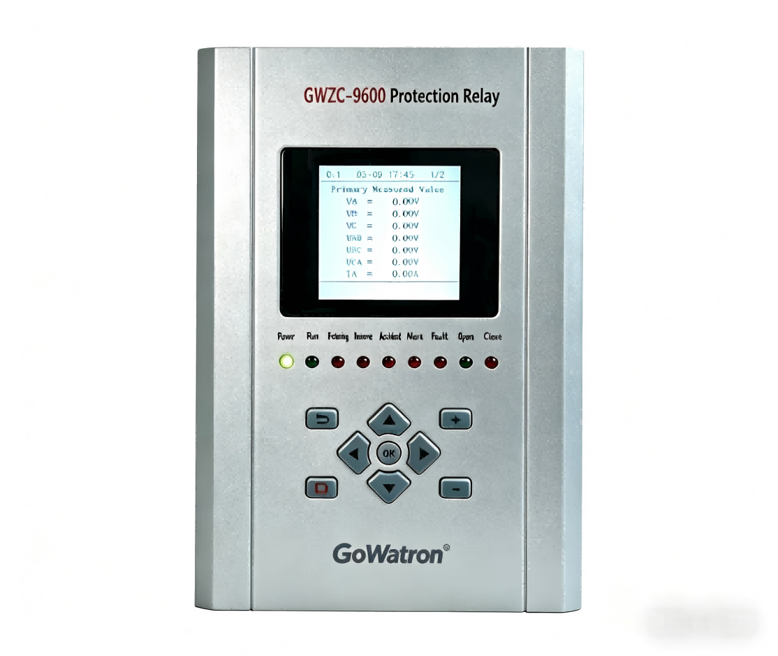
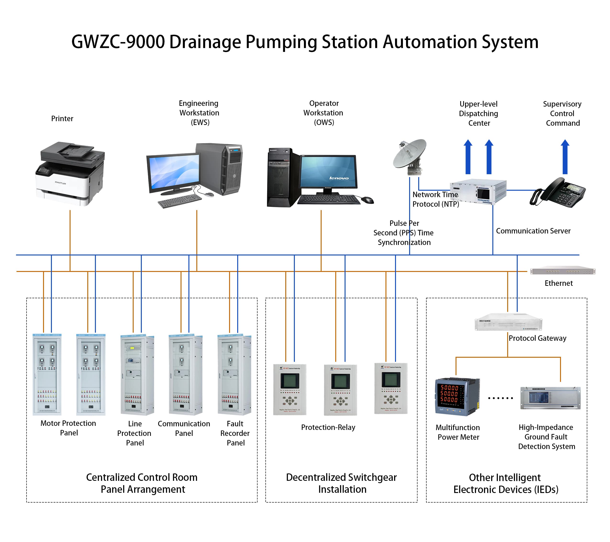
Product Introduction:

           The GWZC-9831 Motor Protection Relay is designed for ​industrial asynchronous motors​ operating at ​400V to 10kVvoltage levels, delivering comprehensive ​protection, control, and measurement capabilities. Built on the ​IEC 61850 standard, it integrates core protection functions including thermal overload (ANSI 49), short-circuit (ANSI 50/51), stall protection, and phase unbalance, with support for high-precision electrical parameter monitoring. Equipped with ​dual Ethernet interfaces​ and ​RS-485 communication, it seamlessly integrates into industrial automation systems. Optimized for ​harsh-environment control cabinets​ (incoming/outgoing feeders), it ensures motor security under overload, voltage fluctuations, and fault conditions.

Product functionsANSI):

1.Three-Step Overcurrent Protection (ANSI 50/51)
2.(Instantaneous Overcurrent Protection) — ANSI 50
3.(Definite-Time Overcurrent Protection) — ANSI 51
4.(Inverse-Time Overcurrent Protection) — ANSI 51
5.Inverse-Time Overcurrent Protection (ANSI 51)
6.Overload Protection (ANSI 49)
7.Locked Rotor Protection (ANSI 48)
8.Negative Sequence Overcurrent Stage I (ANSI 46 (Stage I))
9.Negative Sequence Inverse-Time Overcurrent Protection (ANSI 46 )
10.Zero-Sequence Overcurrent Protection (ANSI 51N/50N)
11.Thermal Overload Protection(ANSI 49)
12.Long Start Protection (ANSI 48LR)
13.Motor Starting Block Protection (ANSI 66)
14.Overvoltage Protection (ANSI 59)
15.Undervoltage Protection (ANSI 27)
16.Zero-Sequence Overvoltage Protection (ANSI 59N)
17.Overfrequency Protection (ANSI 81O)
18.Underfrequency Protection (ANSI 81U)
19.VT Fuse Failure Monitor (ANSI 60FL)
20.VT Loss-of-Voltage (ANSI 27X)
21.Control Circuit Supervision (ANSI 74)
22.System Blackout Protection (ANSI 50BF)
23.Non-Electrical Protection (ANSI 38/49T)

Electrical Specifications​

​Power Supply:​​

● AC: 85-264V, 47-63Hz (≤15% THD)
● DC: 100-370V (≤5% ripple)

​Rated AC Parameters:​​

● Voltage: 100V/√3 or 100V
● Current: 5A/1A
● Frequency: 50Hz

​Overload Capacity:

​​● Current Circuit: 2×In continuous | 10×In (10s) | 40×In (1s)
● Voltage Circuit: 1.5×Un continuous

​Power Consumption:​​

● Supply: <10W (static), ≤15W (trip)
● Current Circuit: ≤1VA/phase (5A) / ≤0.5VA/phase (1A)
● Voltage Circuit: ≤0.5VA/phase

​Digital Output:​​

● Dry contact (8A@250VAC / 30VDC)
● Dielectric: 4kVAC (coil-contact), 1kVAC (open contact)
● Operating Time: 5ms (typ) / 8ms (max)
● Mechanical Life: 100k operations

​Protection Performance​

​Operating Range:​​

● Voltage: 0.5-120V (phase)
● Current: 0.02-20×In
● Zero-Seq Current: 0.05-20A
● Frequency: 35-65Hz | Delay: 0-100s

​Accuracy:​​

● Voltage/Current: ±2.5% or ±0.1V/±0.05A (whichever greater)
● Frequency: ±0.01Hz
● Settings: ±2.5%

​Trip Time:​​

● Instantaneous: ≤35ms (≥1.2× setting)
● Time-Delayed: ≤1% of setting or 35ms

Measurement & Monitoring​

​Range:​​

● Voltage: 0.5-120V | Current: 0.02-1.2×In

Accuracy:​​

● V/I: ±0.2% | Frequency: ±0.01Hz | Other: 0.5%
● Time Sync: ≤2ms | SOE: ≤1ms

​Event Recording:​​

● 128 protection trips/operations
● 32 self-tests/fault waveforms (COMTRADE)

​Environmental & Mechanical​

​Operating Temp:​​

● Standard: -10°C to +55°C
● Extended: -40°C to +70°C*

​Storage Temp:​​ -40°C to +80°C
​Humidity:​​ 5-90% RH (non-condensing)
​Pressure:​​ 60-110 kPa
​Compliance:​​

● IEC 60255-21 (vibration/shock)
● IEC 61000-6 (EMC)

Related products More
GWZC-9631 Motor Protection Relay
detail
GWZC-9833 Motor Magnetic Balance Differential Protection Relay (87M)
GWZC-9833 Motor Magnetic Balance Differential Protection Relay
detail
GWZC-9832 Motor Differential Protection Relay (87M)
GWZC-9832 Motor Differential Protection Relay GWZC-983
detail
GWZC-9000 Sewage Treatment Automation Control System
detail
GWZC-9000 Drainage Pumping Station Automation System
detail
Technical Knowledge More
Automatic Transfer Switch (ATS) Side View
What is Parallel Operation
​Parallel operation​ involves connecting two or more independent AC power sources (e.g., generators, grids) to share electrical loads seamlessly. This process—synchronization—demands precise matching of voltage magnitude, frequency, and phase angles between systems before interconnection. Critical for grid expansion, backup power, and renewable integration, it enables redundant supply during failures.
2025/08/15
Generator-Transformer Differential Protection Relay Rear View
Ring-Closing Operation: Definition & Importance in Power Grids
A ring-closing operation involves closing a normally open switch within a closed-loop electrical network fed by a single power source. This creates parallel paths to redistribute loads without interruption, primarily for maintenance or network reconfiguration. Key prerequisites are voltage difference under 5%, phase angle alignment below 5 degrees, and pre-calculation of induced circulating currents to avoid equipment damage. Distinct from connecting independent systems, this procedure requires advanced monitoring but avoids synchronization complexity. Strict protocols using real-time sensors and simulations ensure safe execution, making it fundamental for resilient distribution networks like ring-main units (RMUs) in urban grids.
2025/08/14
Synchronism Check Function vs. Synchronizing Function: Roles, Differences, and Applications
This article compares the ​synchronism check function​ in line protection devices and the ​synchronizing function​ in dedicated synchronizing equipment. The ​synchronism check function​ serves as a safety interlock for circuit breaker closing operations, while the ​synchronizing function​ enables precise generator synchronization and critical tie-line interconnections with active parameter regulation. Explore core principles, application scenarios, and technical distinctions between these critical power system components.
2025/08/11
GWZC-9831 Motor protection relay
Motor protection relay Side View
Motor protection relay Rear View
Inquiry Consultation
产品表单
Inquiry Consultation
+86-17621210051
+86-17621210051
+86-17621210051
+86-17621210051
home product email
live chat
my