Back to smartelemfg Home
Contact us Merchants settle in
Back to smartelemfg Home
Home -Line protection relay
GWZC-9811  Line protection relay
Line protection relay Side View
Line protection relay Rear View
GWZC-9811  Line protection relay
Line protection relay Side View
Line protection relay Rear View
GWZC-9811 Line protection relay

Applicable Scope:The ​GWZC-9811 Line Protection Relay​ provides overcurrent, earth fault, and short-circuit protection for ​10kV–35kV transmission lines and feeders, typically installed in ​switchgear panels, feeder cabinets, or ring main units (RMUs)​. It ensures reliable fault detection and isolation in ​industrial, utility, and renewable energy systems, enhancing grid stability and reducing downtime.

Product functions(ANSI):50/50V/50N | 51/51V/51NI | 67/67N | 81/81R/81U | 49 | 27 | 79 | 74 | 59/59N

Communication functions:Supported Protocols:​​IEC 60870-5-103 (over Ethernet) | MODBUS RTU (via RS-485) | IEC 61850 (Ed.2 or Ed.1, as applicable)
​Interfaces:​​2× Ethernet Ports​ (IEEE 802.3 compliant, 10/100 Mbps) | | 2× RS-485 Ports​ (ANSI/TIA-485-A standard, galvanically isolated)

Other functions: Support time synchronization via communication message, SNTP (Simple Network Time Protocol) time synchronization, and IRIG-B time synchronization. Support the dot matrix printing function with serial port communication. Support the fault recording function

Product Introduction Technical Parameter Size

Product Introduction:

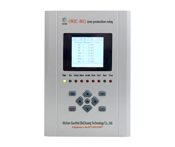
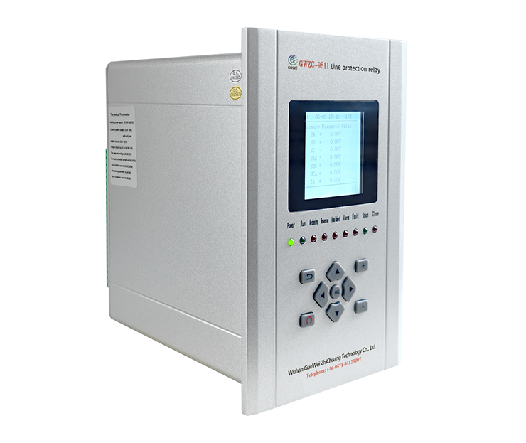
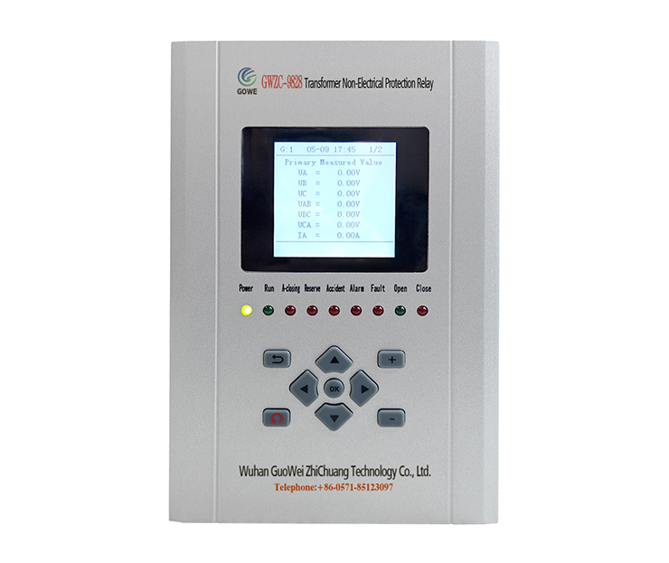
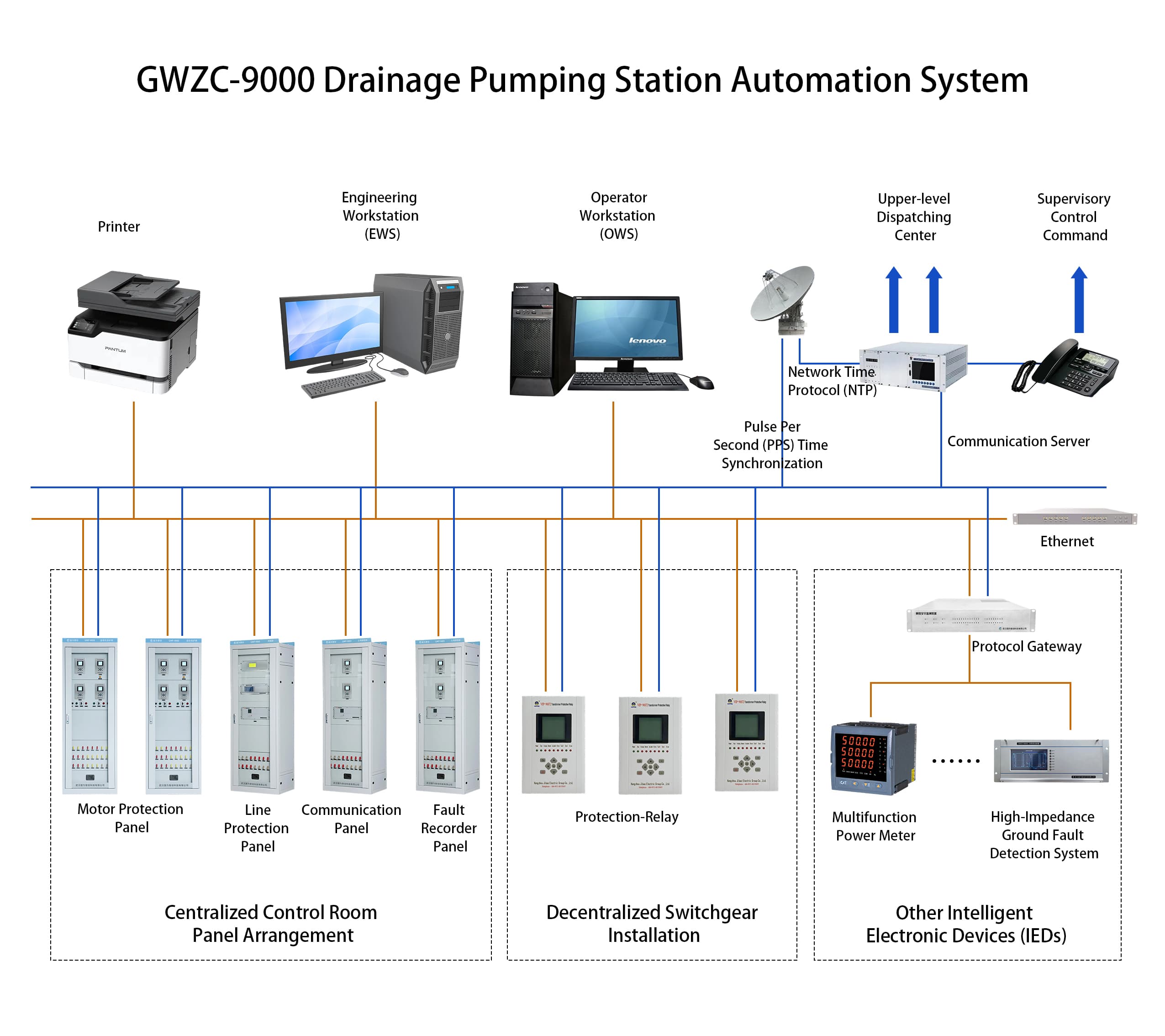
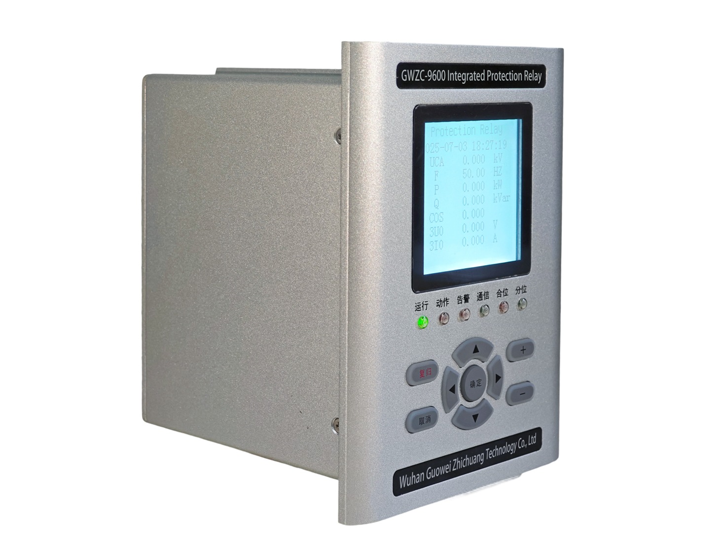
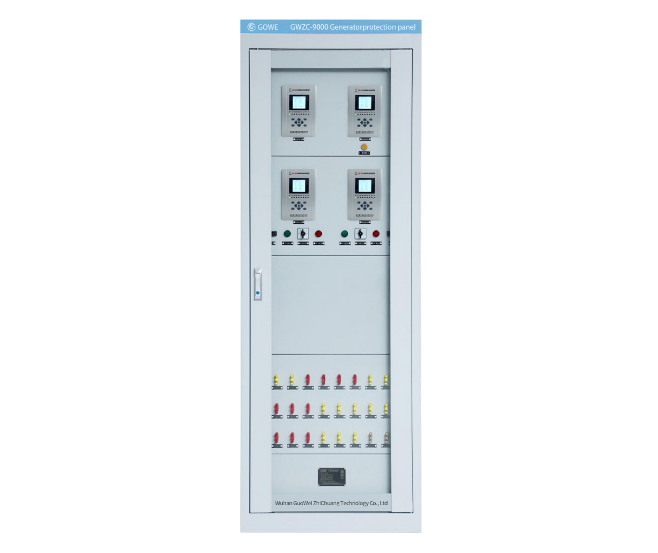
       The VIP-9811 Line Protection Relay is designed for protection, control, and measurement of transmission lines at voltage levels of 132kV, 66kV, 33kV, and 11kV. It is widely applied in substations, distribution stations, and power plants for the protection and control of incoming feeder cabinets and outgoing feeder cabinets.

Product functions

1.Instantaneous Overcurrent Protection (ANSI 50)(Trip)

      Voltage-Controlled Instantaneous OC Protection (ANSI 50V ) 

      Directional Blocked Instantaneous OC Protection (ANSI 67 ) 

2.Time – limitedInstantaneous Overcurrent Protection (ANSI 50)  (Trip)

      Voltage-Restrained Time-Delayed Overcurrent Protection (ANSI 51V )

      Directional Definite-Time Overcurrent Protection (ANSI 67 ) 

3.Definite – Time Overcurrent Protection(ANSI 51) (Trip)

      Voltage-Controlled Definite-Time Overcurrent Protection (ANSI 51V ) 

      Directional Definite-Time Overcurrent Protectionn (ANSI 67 ) 

4.Inverse-Time Overcurrent Protection (ANSI 51AC)(Trip)

      Voltage-Restrained Inverse-Time OC Protection (ANSI 51V ) 

      Directional Inverse-Time OC Protection (ANSI 67 ) 

5.Reclosing Acceleration Protection(ANSI: 79+50/67) (Trip)

      Voltage-Controlled Reclosing Acceleration Protection (ANSI:79 + 50V/51V)

      Directional Blocked Reclosing Acceleration Protection(ANSI:79 + 67)

6.Overload Protection(ANSI 49)(Alarm/Trip)

7.InstantaneousZero-Sequence Overcurrent Protection(ANSI: 50N)(Trip)

      Zero-Sequence Under-Voltage Blocked Instantaneous Zero-Sequence Overcurrent Protection(ANSI:50NZ)

      Directional Blocked Instantaneous Zero-Sequence Overcurrent Protection(ANSI: 67N)

8.Time – limitedZero-Sequence Overcurrent Protection (ANSI: 51N) (Trip)

      Zero-Sequence Under-Voltage Blocked Definite-Time Zero-Sequence Overcurrent Protection(ANSI:51NZ)

      Directional Blocked Definite-Time Zero-Sequence Overcurrent Protection (ANSI;67N)

9.Definite-Time Zero-Sequence Overcurrent Protection(ANSI:51N)(Alarm/Trip)

10.Inverse-Time Zero-SequenceOvercurrent Protection (ANSI:51NI) (Trip)

Electrical Specifications​

​Power Supply:​​

● AC: 85-264V, 47-63Hz (≤15% THD)
● DC: 100-370V (≤5% ripple)

​Rated AC Parameters:​​

● Voltage: 100V/√3 or 100V
● Current: 5A/1A
● Frequency: 50Hz

​Overload Capacity:​​

● Current Circuit: 2×In continuous | 10×In (10s) | 40×In (1s)
● Voltage Circuit: 1.5×Un continuous

​Power Consumption:​​

● Supply: <10W (static), ≤15W (trip)
● Current Circuit: ≤1VA/phase (5A) / ≤0.5VA/phase (1A)
● Voltage Circuit: ≤0.5VA/phase

​Digital Output:​​

● Dry contact (8A@250VAC / 30VDC)
● Dielectric: 4kVAC (coil-contact), 1kVAC (open contact)
● Operating Time: 5ms (typ) / 8ms (max)
● Mechanical Life: 100k operations

​Protection Performance​

Operating Range:​​

● Voltage: 0.5-120V (phase)
● Current: 0.02-20×In
● Zero-Seq Current: 0.05-20A
● Frequency: 35-65Hz | Delay: 0-100s

​Accuracy:​​

● Voltage/Current: ±2.5% or ±0.1V/±0.05A (whichever greater)
● Frequency: ±0.01Hz
● Settings: ±2.5%

​Trip Time:​​

● Instantaneous: ≤35ms (≥1.2× setting)
● Time-Delayed: ≤1% of setting or 35ms

Measurement & Monitoring​

​Range:​​

● Voltage: 0.5-120V | Current: 0.02-1.2×In

​Accuracy:​​

● V/I: ±0.2% | Frequency: ±0.01Hz | Other: 0.5%
● Time Sync: ≤2ms | SOE: ≤1ms

​Event Recording:​​

● 128 protection trips/operations
● 32 self-tests/fault waveforms (COMTRADE)

​Environmental & Mechanical​

​Operating Temp:​​

● Standard: -10°C to +55°C
● Extended: -40°C to +70°C*
​Storage Temp:​​ -40°C to +80°C

​Humidity:​​ 5-90% RH (non-condensing)
​Pressure:​​ 60-110 kPa
​Compliance:​​

● IEC 60255-21 (vibration/shock)
● IEC 61000-6 (EMC)

Related products More
GWZC-9812 Distance protection relay(21 | 21G | 21FL)
GWZC-9812 Distance protection relay
detail
GWZC-9611 Feeder Protection Relay
detail
GWZC-9913 FO Line Diff Relay(87L)
detail
GWZC-9916 Bus differential protection relay
detail
GWZC-9811C Line differential protection relay (87H | 87)
GWZC-9811C Line differential protection relay
detail
Technical Knowledge More
Wireless Temperature Monitoring System for Substations
Wireless Temperature Monitoring System: Application in Switchgear​
This article introduces the application of wireless temperature monitoring systems in high-voltage and low-voltage switchgear. The configuration of the wireless temperature monitoring system varies across different equipment. If you need a customized wireless temperature monitoring solution for your project, please visit our website for more information.
2025/09/08
GWZC-9804 Arc Flash Protection Relay
Switchgear Arc Flash Protection System Configuration Scheme
This article introduces the configuration scheme for a switchgear arc flash protection system. Busbar arc flash protection monitors the busbar compartment and trips the incoming breaker, while feeder arc flash protection monitors the circuit breaker compartment and cable compartment to trip the feeder breaker. A proper arc flash protection system configuration scheme can effectively protect personnel and equipment safety. For information on a reliable arc flash protection system configuration scheme, please visit our website.
2025/09/04
Arc Flash Protection Relay
Arc Protection Working Principle and Decision Process
Arc Flash Protection is a specialized safety system engineered to rapidly detect and mitigate destructive electrical arc flash faults. Unlike conventional overcurrent protection, it utilizes a combination of light and current sensors to identify an arc flash event within milliseconds. By triggering a circuit breaker to isolate the fault incredibly fast, Arc Flash Protection significantly reduces the explosive energy released, safeguarding personnel from severe injury and preventing extensive damage to electrical equipment like switchgear. This makes it an indispensable defense layer in industrial, commercial, and utility power systems.
2025/09/03
GWZC-9811  Line protection relay
Line protection relay Side View
Line protection relay Rear View
Inquiry Consultation
产品表单
Inquiry Consultation
+86-17621210051
+86-17621210051
+86-17621210051
+86-17621210051
home product email
live chat
my