Back to smartelemfg Home
Contact us Merchants settle in
Back to smartelemfg Home
Home -Differential protection relay
GWZC-9811C Line differential protection relay
Line differential protection relay Side View
Line differential protection relay Rear View
GWZC-9811C Line differential protection relay
Line differential protection relay Side View
Line differential protection relay Rear View
GWZC-9811C Line differential protection relay (87H | 87)

Applicable Scope:The GWZC-9811C line differential protection relay is specifically designed for power distribution systems up to 66kV, utilizing pilot-wire differential protection technology for rapid fault clearance. This device is suitable for installation in substation switchgear cabinets, providing primary protection for critical feeders, industrial circuits, and ring-main systems.

Product functions(ANSI)87H | 87 | 87A | 50 | 51 | 51V | 49 | 46 | 50N/50G | 59 | 27 | 81 | 30

Communication functions : Supported Protocols:​​IEC 60870-5-103 (over Ethernet) | MODBUS RTU (via RS-485) | IEC 61850 (Ed.2 or Ed.1, as applicable)
​Interfaces:​​2× Ethernet Ports​ (IEEE 802.3 compliant, 10/100 Mbps) | 2× RS-485 Ports​ (ANSI/TIA-485-A standard, galvanically isolated)

Other functions: Support time synchronization via communication message, SNTP (Simple Network Time Protocol) time synchronization, and IRIG-B time synchronization. Support the dot matrix printing function with serial port communication. Support the fault recording function

Product Introduction Technical Parameter Size

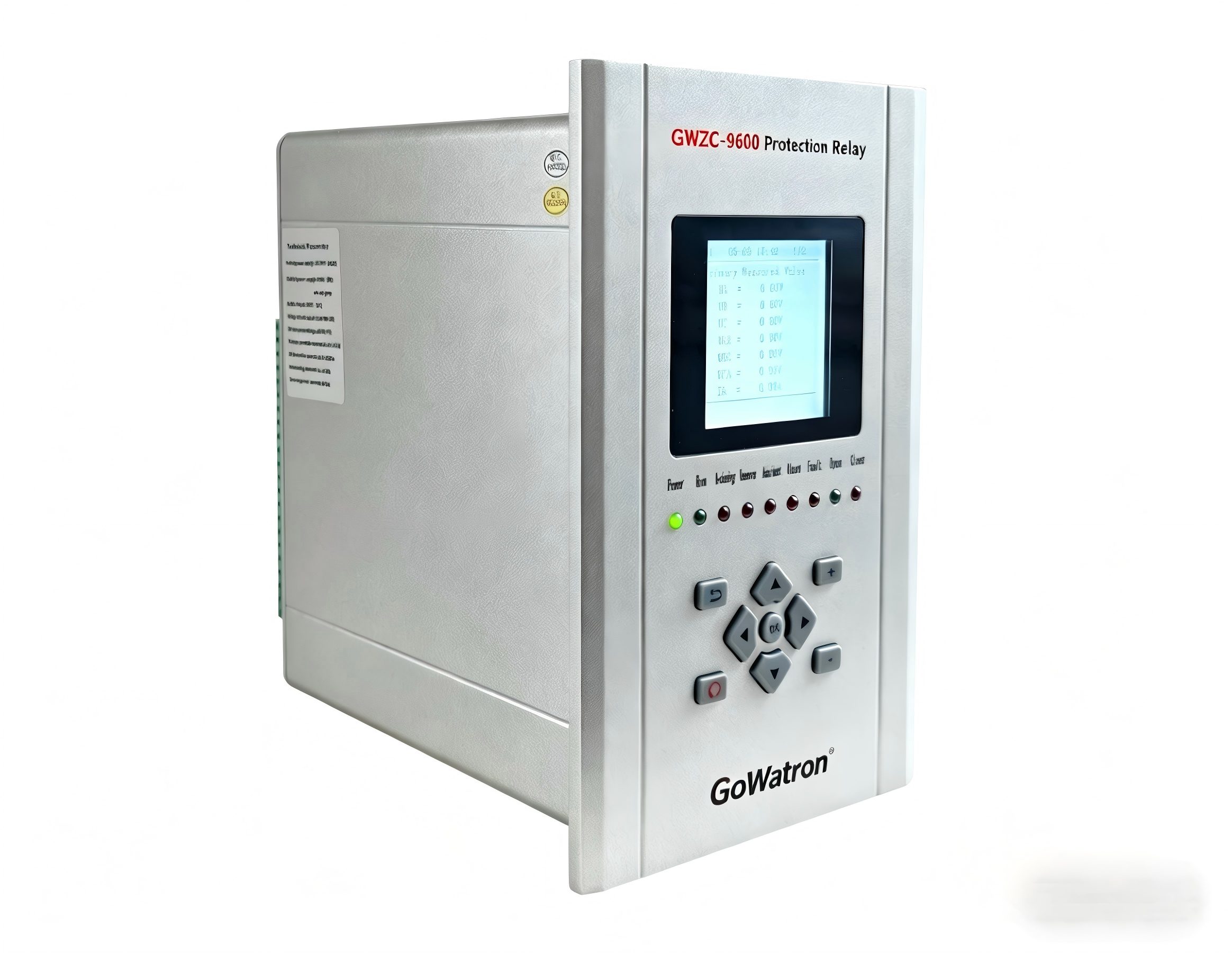
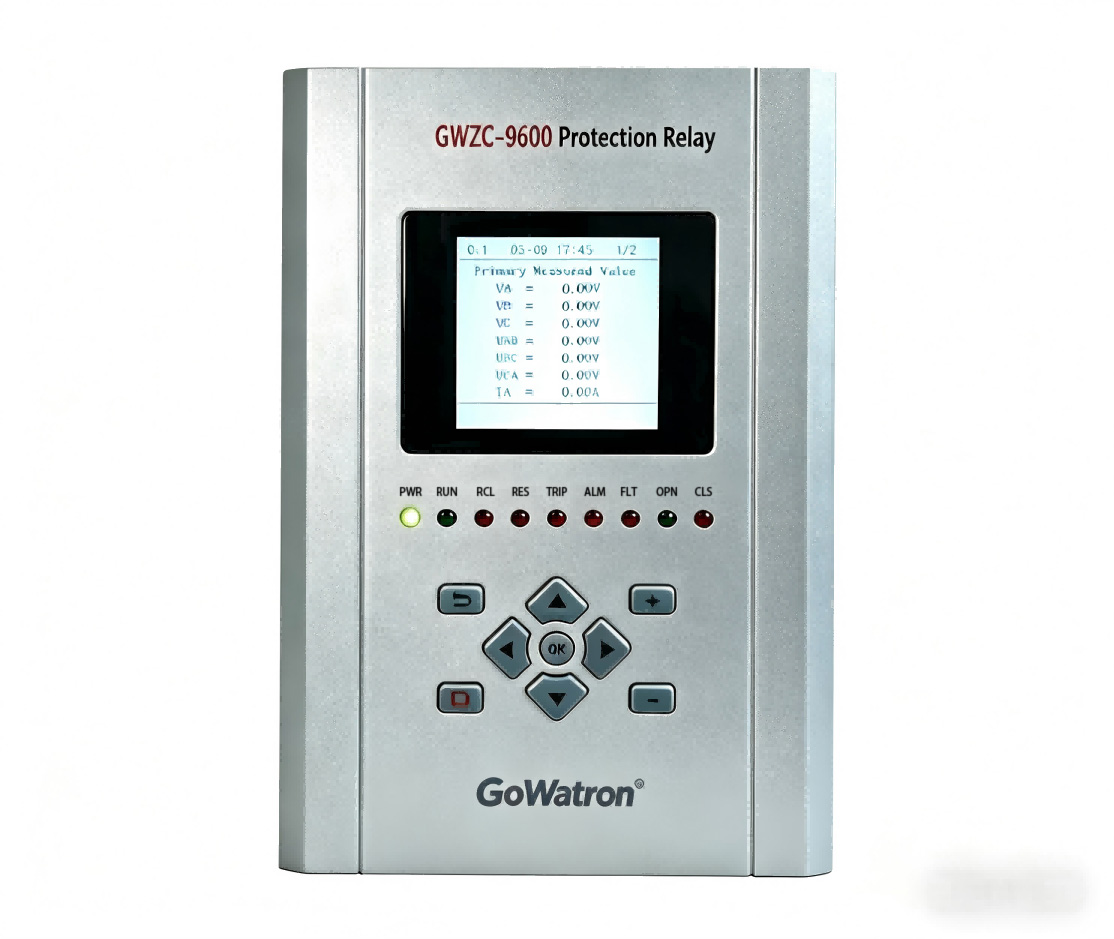
Product Introduction:

          The GWZC-9811C line differential protection relay is specifically designed for 66kV and below distribution networks, featuring pilot-wire based current differential protection that ensures rapid fault clearance to enhance power supply reliability. This relay is primarily installed in distribution substation switchgear cabinets and is suitable for critical feeders, industrial power lines, and ring main systems, providing both primary differential protection and backup overcurrent protection along with fault recording capabilities, while offering the advantages of simple wiring and cost-effective reliability.

Product functionsANSI):

1.High-Speed Differential Protection (ANSI 87H)
2.Percentage Differential Protection (ANSI 87)
3.Differential Current Alarm (IEEE C37.2 Device 87A)
4.Instantaneous Overcurrent Protection (ANSI 50)
5.Time-Delayed Overcurrent Protection (ANSI 51)
6.Time-Delayed Overcurrent Protection (ANSI 51)
7.Inverse Time Overcurrent Protection (ANSI 51V)
8.​Overload Protection (ANSI 49)
9.Negative Sequence Instantaneous Overcurrent Protection (ANSI 46)
10.Negative Sequence Time-Delayed Overcurrent Protection (ANSI 46)
11.Instantaneous Ground (Zero Sequence) Overcurrent Protection (ANSI 50N/50G)
12.Time-Delayed Ground (Zero Sequence) Overcurrent Protection (ANSI 51N/51G)
13.Time-Delayed Ground (Zero Sequence) Overcurrent Protection (ANSI 51N/51G)
​14.Overvoltage Protection (ANSI 59)
15.Undervoltage Protection (ANSI 27)
16.Residual Overvoltage Protection (ANSI 59N)
17.Potential Transformer Fuse Failure / PT Supervision (IEEE C37.2 Device 60FL)
18.Potential Transformer Loss of Voltage (IEEE C37.2 Device 60FL)
19.Current Transformer Supervision (IEEE C37.2 Device 60CTS)
20.Control Circuit Supervision / Trip Circuit Supervision (IEEE C37.2 Device 74)
21.Loss of Mains / Underfrequency Protection (ANSI 81)
22.Non-Electrical Protection (ANSI 30)

Electrical Specifications​

​Power Supply:​​

● AC: 85-264V, 47-63Hz (≤15% THD)
● DC: 100-370V (≤5% ripple)

​Rated AC Parameters:​​

● Voltage: 100V/√3 or 100V
● Current: 5A/1A
● Frequency: 50Hz

​Overload Capacity:​​

● Current Circuit: 2×In continuous | 10×In (10s) | 40×In (1s)
● Voltage Circuit: 1.5×Un continuous

​Power Consumption:​​

● Supply: <10W (static), ≤15W (trip)
● Current Circuit: ≤1VA/phase (5A) / ≤0.5VA/phase (1A)
● Voltage Circuit: ≤0.5VA/phase

​Digital Output:​​

● Dry contact (8A@250VAC / 30VDC)
● Dielectric: 4kVAC (coil-contact), 1kVAC (open contact)
● Operating Time: 5ms (typ) / 8ms (max)
● Mechanical Life: 100k operations

​Protection Performance​

​Operating Range:​​

● Voltage: 0.5-120V (phase)
● Current: 0.02-20×In
● Zero-Seq Current: 0.05-20A
● Frequency: 35-65Hz | Delay: 0-100s

​Accuracy:​​

● Voltage/Current: ±2.5% or ±0.1V/±0.05A (whichever greater)
● Frequency: ±0.01Hz
● Settings: ±2.5%

​Trip Time:​​

● Instantaneous: ≤35ms (≥1.2× setting)
● Time-Delayed: ≤1% of setting or 35ms

​Measurement & Monitoring​

​Range:​​

● Voltage: 0.5-120V | Current: 0.02-1.2×In

​Accuracy:​​

● V/I: ±0.2% | Frequency: ±0.01Hz | Other: 0.5%
● Time Sync: ≤2ms | SOE: ≤1ms

​Event Recording:​​

● 128 protection trips/operations
● 32 self-tests/fault waveforms (COMTRADE)

​Environmental & Mechanical​

​Operating Temp:​​

● Standard: -10°C to +55°C
● Extended: -40°C to +70°C*

​Storage Temp:​​ -40°C to +80°C
​Humidity:​​ 5-90% RH (non-condensing)
​Pressure:​​ 60-110 kPa

​Compliance:​​

● IEC 60255-21 (vibration/shock)
● IEC 61000-6 (EMC)

Related products More
GWZC-9913 FO Line Diff Relay(87L)
detail
GWZC-9916 Bus differential protection relay
detail
GWZC-9884 Generator Differential Protection Relay(87H | 87 | 87A)
GWZC-9884 Generator Differential Protection Relay
detail
GWZC-9826 Main Transformer Differential Protection Relay(87H | 87 | 87A)
GWZC-9826 Main Transformer Differential Protection Relay
detail
GWZC-9833 Motor Magnetic Balance Differential Protection Relay (87M)
GWZC-9833 Motor Magnetic Balance Differential Protection Relay
detail
Technical Knowledge More
Wireless Temperature Monitoring System for Substations
Wireless Temperature Monitoring System: Application in Switchgear​
This article introduces the application of wireless temperature monitoring systems in high-voltage and low-voltage switchgear. The configuration of the wireless temperature monitoring system varies across different equipment. If you need a customized wireless temperature monitoring solution for your project, please visit our website for more information.
2025/09/08
GWZC-9804 Arc Flash Protection Relay
Switchgear Arc Flash Protection System Configuration Scheme
This article introduces the configuration scheme for a switchgear arc flash protection system. Busbar arc flash protection monitors the busbar compartment and trips the incoming breaker, while feeder arc flash protection monitors the circuit breaker compartment and cable compartment to trip the feeder breaker. A proper arc flash protection system configuration scheme can effectively protect personnel and equipment safety. For information on a reliable arc flash protection system configuration scheme, please visit our website.
2025/09/04
Arc Flash Protection Relay
Arc Protection Working Principle and Decision Process
Arc Flash Protection is a specialized safety system engineered to rapidly detect and mitigate destructive electrical arc flash faults. Unlike conventional overcurrent protection, it utilizes a combination of light and current sensors to identify an arc flash event within milliseconds. By triggering a circuit breaker to isolate the fault incredibly fast, Arc Flash Protection significantly reduces the explosive energy released, safeguarding personnel from severe injury and preventing extensive damage to electrical equipment like switchgear. This makes it an indispensable defense layer in industrial, commercial, and utility power systems.
2025/09/03
GWZC-9811C Line differential protection relay
Line differential protection relay Side View
Line differential protection relay Rear View
Inquiry Consultation
产品表单
Inquiry Consultation
+86-17621210051
+86-17621210051
+86-17621210051
+86-17621210051
home product email
live chat
my