Back to smartelemfg Home
Contact us Merchants settle in
Back to smartelemfg Home
Home -Numeric protection panel​
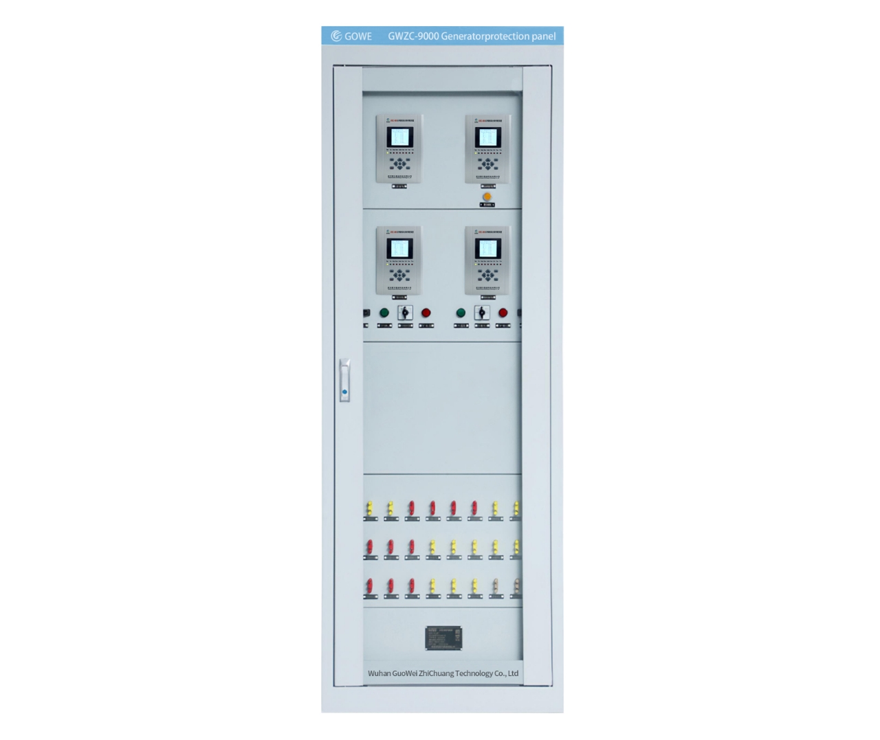
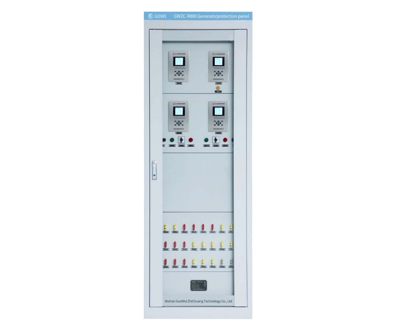
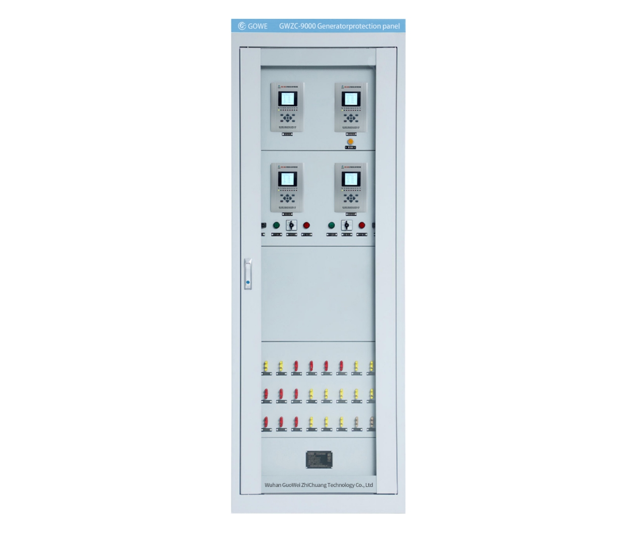
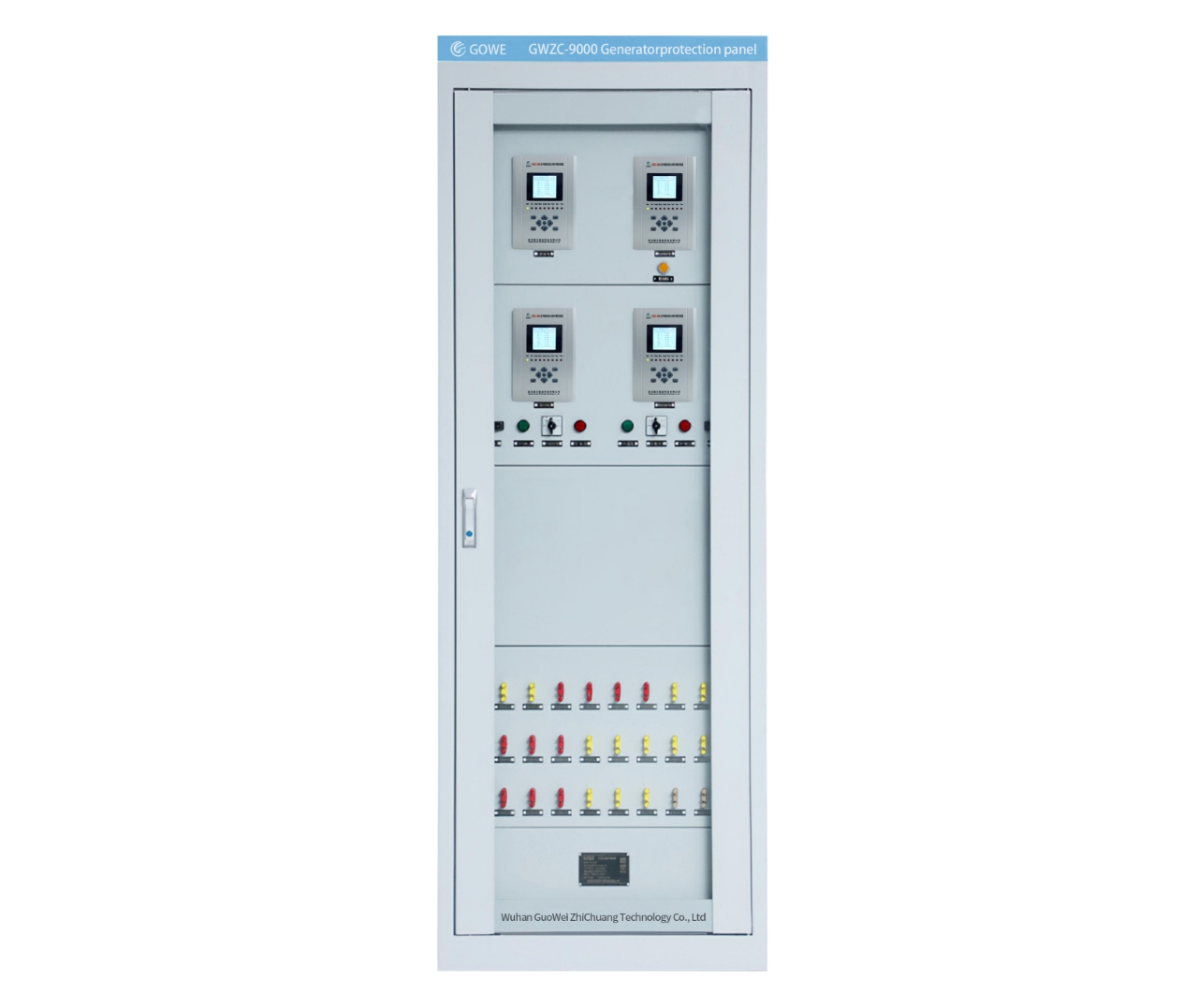
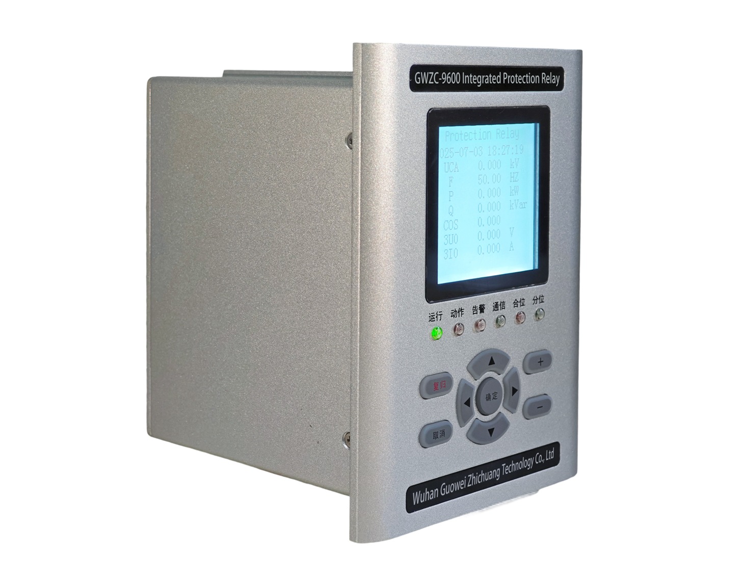
GWZC-9000 Fault recorder panel (​FRP) (ANSI 21)

Introduction : The Fault Recorder Panel (FRP) serves as the “black box” of power systems, capturing real-time voltage/current waveforms and digital signals during faults to provide critical data for fault analysis and protection verification. ​(ANSI 21)

Communication protocols : ​IEC 60870-5-101/103/104 ,IEC 61850(MMS/GOOSE/SV), Modbus RTU​ & ​Modbus TCP​,RJ-45 , RS-485

Product Introduction Technical Parameter Size

1. Key Functions of Fault Recorder Panel​

​​(1) Fault Recording & Analysis​
          Captures voltage/current waveforms during short-circuit, grounding, or line-break faults.
          Records pre-fault and post-fault data (seconds to minutes) for root cause analysis.

​​(2) Protection Device Verification​
          Logs relay and circuit breaker operation sequences to validate protection schemes (e.g., ANSI/IEEE C37.111 compliance).

​​(3) Power Quality Monitoring​
          Detects harmonics, voltage sags/swells, and frequency deviations per ​IEC 61000-4-30.

​2. Core Features of Fault Recorder Panel​

​​(1) Multi-Channel High-Speed Sampling​
          Supports simultaneous acquisition of analog (voltage/current via ​PT/CT) and digital inputs (breaker status, relay signals).
          Sampling rates range from ​kHz to MHz​ for transient analysis.

​​(2) Triggered Recording​
          Auto-activates upon thresholds (overcurrent, voltage distortion, frequency deviation) per ​IEEE 1344.

(3) Data Storage & Compression​
          Employs ​FIFO (First-In-First-Out) buffering; prioritizes fault data storage in ​COMTRADE format (IEEE C37.111)​.

​​(4) Time Synchronization​
          Uses ​GPS/IEEE 1588 (PTP)​​ or ​IRIG-B​ for μs-level synchronization across substations.

​​(5) HMI & Connectivity​
          Features touchscreen/buttons for waveform replay, setting adjustments, and report generation.
          Exports data via ​Ethernet, USB, or fiber optics​ to ​SCADA/EMS systems.

​3. Working Principle of Fault Recorder Panel​

​​(1) Signal Acquisition​
          ​PT/CT Isolation: Steps down HV/high-current signals to low-level inputs.
          ​A/D Conversion: Analog signals are filtered, amplified, and digitized by ​16-bit+ ADCs.

​​(2) Data Processing​
          ​Trigger Logic: Real-time monitoring via ​FPGA/DSP; triggers recording upon fault detection.
          ​Buffer Memory: High-speed ​RAM​ temporarily stores sampled data.

​​(3) Storage & Output​
          Timestamped data saved in ​COMTRADE​ format for compatibility .
          Supports ​IEC 61850​ communication for seamless grid integration.

​​(4) Redundant Power Supply​
          Dual feeds (AC/DC) ensure uninterrupted operation during faults.

Related products More
GWZC-9000 Busbar Protection Panel
detail
GWZC-9000 Power measurement and control panel
detail
GWZC-9000 Low-voltage load shedding panel
Low-voltage load shedding panel
detail
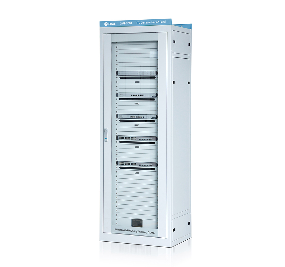
GWZC-9000 Remote Terminal Unit (RTU) Communication Panel
RTU Communication Panel
detail
GWZC-9000 Main Transformer Protection Panel
Main Transformer Protection Panel
detail
Technical Knowledge More
Generator Rotor Single-Point Grounding Protection
Working Principle, Function, and Setting Value Calculation of Generator Rotor Single-Point Grounding Protection (64F)
The core principle of rotor earth fault protection is to monitor the insulation condition of the generator's field circuit (rotor circuit) to ground. Under normal conditions, the rotor circuit is insulated from ground, with only a very small leakage current to earth. A single earth fault does not create a short-circuit path (as a return path is missing), but it serves as a critical alarm because a subsequent second earth fault would have severe consequences.
2025/10/17
GWZC-9000-Hydropower-Plant-Automation-System
Composition of a Hydropower Plant Integrated Automation System
       The main components of a hydropower plant integrated automation system are as follows: 1. Station Level / Control and Monitoring Level This is the "brain" of the entire system, located in the central control room, responsible for plant-wide supervision, control, management, and communication.
2025/10/17
Generator-Comprehensive-Protection-Relay
Protection Functions for Protection Relays of Large Diesel Generators (1000-2000KW)
 The protection system for large diesel generators (1000-2000KW) shall be equipped with the following protection functions:         Overcurrent Protection (ANSI 50/51): Prevents damage to the generator set caused by overload or short circuit.        Overvoltage Protection (ANSI 59): Protects the windings and insulation of the generator set from damage caused by overvoltage.        Undervoltage Protection (ANSI 27): Ensures the generator set trips in a timely manner when the voltage is too low to avoid equipm
2025/10/14
Inquiry Consultation
产品表单
Inquiry Consultation
+86-17621210051
+86-17621210051
+86-17621210051
+86-17621210051
home product email
live chat
my