Capacitor Protection Relay Product Introduction:
The GWZC-9541 Capacitor Protection Relay is designed to safeguard shunt capacitor banks in medium-voltage distribution networks, providing essential functions such as overcurrent, over/undervoltage, unbalance, and thermal overload protection, along with inrush current restraint to prevent false tripping during energization.
The GWZC-9541 Capacitor Protection Relay is widely used in substations, industrial plants, and renewable energy systems for reactive power compensation, power factor correction, and harmonic filtering. Typically installed in capacitor bank control panels or switchgear cubicles, this relay ensures reliable operation by detecting faults, preventing equipment damage, and maintaining system stability in 6.6kV and 11kV power networks.
Product functions(ANSI)
1.Instantaneous Overcurrent Protection (ANSI 50)
2.Time Overcurrent Protection (ANSI 51)
3.Overvoltage Protection (ANSI 59)
4.Undervoltage Protection (ANSI 27)
5.Residual Overcurrent Protection (ANSI 50N/51N)
6.Negative Sequence Overcurrent Protection (ANSI 46)
7.Negative Sequence Overvoltage Protection (ANSI 47)
Technical Features of Capacitor Protection Relay
1.Utilizes an internationally advanced high-speed processor operating at 120 MHz. With abundant built-in resources and simplified peripheral circuit design, it ensures superior manufacturing quality and stability. Ample hardware resources include 8MB Flash Memory.
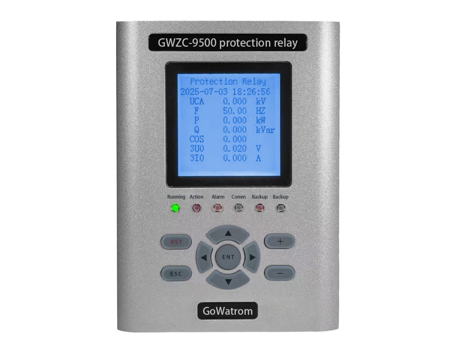
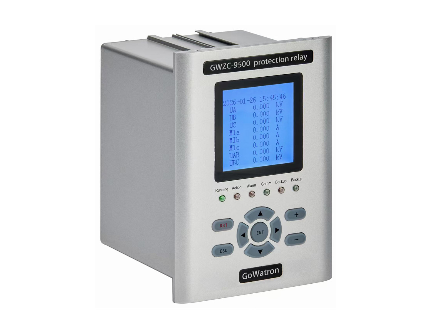
2.Measures three-phase currents and zero-sequence current (Ia, Ib, Ic, Io), phase or line voltages (Uan, Ubn, Ucn, Uab, Ubc, Uca), active power P, reactive power Q, power factor cosφ, frequency f, active energy kWh, and reactive energy kVarh.
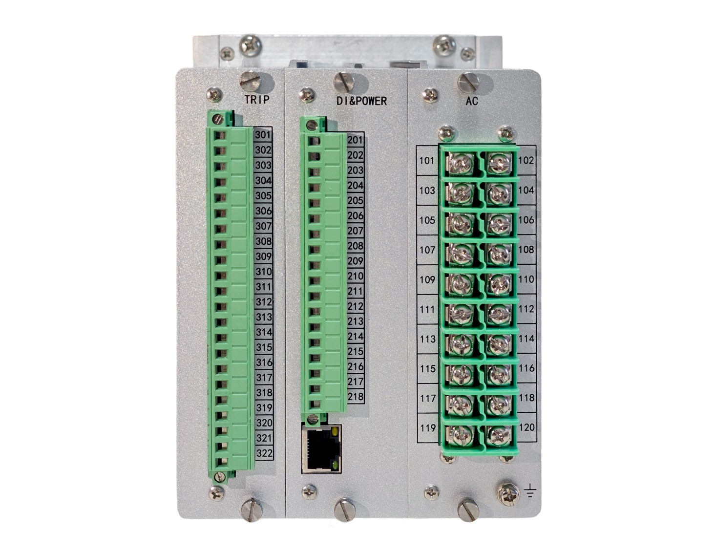
3.Supports up to 12 user-customizable binary inputs with configurable labels.
4.Protection element tripping logic is programmable via trip matrix, enabling flexible relay output assignment. All relay outputs can be configured as trip contacts (auto-reset) or alarm contacts (manual reset).
5.Built-in universal operating circuit compatible with 0.5A–5A tripping/closing currents and AC/DC power supplies.
6.Supports network-based GPS time synchronization.
7.Implements reliable TV failure criteria to prevent unintended motor undervoltage protection operation.
8.Includes one 100M Ethernet port and one RS485 interface, supporting IEC 60870-5-103, Modbus protocols.
9.Records 16 fault waveforms with up to 13 analog channels sampled at 1ms intervals in standard Comtrade format.
10.Low static power consumption (≈6W). LCD module employs new technology for significantly extended service life.
11.High EMC immunity, passing 10 tests including Level IV (highest) standards for fast transients, electrostatic discharge, and surge immunity.
12.Operating temperature: -25℃ to +55℃ (ensuring clear display and smooth operation).
Technical Specifications and Parameters of Capacitor Protection Relay
1.Rated Electrical Parameters
Power Supply
Operating voltage: AC/DC 86V–264V
Ripple factor: ≤5%.
Rated Current & Voltage
AC current: 5A or 1A;
AC voltage: 100V or 100/√3V.
2.Key Technical Indicators
Accurate Operating Range
Current: 0.04In–20In (In=5A or In=1A);
Voltage: 1V–150V;
Frequency: 45Hz–60Hz.
Measurement Accuracy
Voltage/current: Class 0.5;
Active/reactive power, power factor: Class 1.0;
Frequency: ≤±0.05Hz;
Setting Error
Setting value: ≤±3%;
Operating time error:
Definite-time protection: ≤(±1% setting +40)ms
Inverse-time protection: ≤±5% setting or ±40ms.
SOE Resolution
<2ms.
Contact Capacity
Trip/closing current of operating circuit: 0.5A–5A adaptive; compatible with AC/DC trip circuits.
Trip dry contact: 8A (make capacity at DC220V);
Signal dry contact: 5A (make capacity at DC220V).
3.Environmental Conditions
Ambient temperature: -25℃ to +70℃;
Relative humidity: 5%–95% (no condensation/icing internally);
Atmospheric pressure: 66kPa–106kPa.
4.Power Consumption
AC current circuit: ≤0.5VA/phase at In=5A; ≤0.3VA/phase at In=1A.
AC voltage circuit: ≤0.5VA/phase at rated voltage.
DC power circuit: ≤10W (normal operation); ≤20W (during activation).
5.Overload Capacity
AC current circuit:
2×In continuous
10×In for 10s
40×In for 1s.
AC voltage circuit: 1.4×Un continuous.
6.Insulation Performance
Insulation Resistance
≥100MΩ between electrified terminals and non-charged metal parts/enclosure, and between independent circuits (measured with 500V megger under standard conditions).
Dielectric Strength
Withstands 50Hz AC voltage for 1min without breakdown/flashover (remaining circuits grounded during test).
Impulse Voltage
Withstands 1.2/50μs lightning impulse voltage:
5kV (open-circuit) between independent circuits or between circuits and ground.
7.Damp Heat Endurance
Passes GB/T 7261 alternating damp heat test:
+40±2℃, RH 93±3%, 48h (24h/cycle).
Insulation resistance measured during last 2h: ≥1.5MΩ;
Dielectric strength: ≥75% of specified test voltage.